Continue to Site

Welcome to EDAboard.com

Welcome to our site! EDAboard.com is an international Electronics Discussion Forum focused on EDA software, circuits, schematics, books, theory, papers, asic, pld, 8051, DSP, Network, RF, Analog Design, PCB, Service Manuals... and a whole lot more! To participate you need to register. Registration is free. Click here to register now.

Is it okay to have no current limiting resistor with LEDs?

Status
Not open for further replies.

Jay_

Member level 3
Member level 3
Joined
Aug 23, 2010
Messages
56
Helped
1
Reputation
2
Reaction score
2
Trophy points
1,288
Activity points
1,779
Hi, I just had a simple question. If I have a 1.5 volt battery source and 1 V rated LEDs, is it okay for me to have a ladder of 20 rungs, with each rung having 2 LEDs in series WITHOUT a current limiting resistor?

I also know that it would be better for me to have a constant current source, or a PWM at high frequency to use the LEDs to maximum efficiency. But do I need a current limiting resistor? Because if I do place one, I will be wasting a lot of energy through the resistor and I also figured that the voltage across both the LEDs in any rung is 1.5 V which is less than 1 + 1 = 2V. Also if I connect only one LED in a rung with a series resistor (to dissipate the 0.5 V), I will be wasting a lot of my battery energy through the resistor. Untitled.png
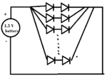
 

I also figured that the voltage across both the LEDs in any rung is 1.5 V which is less than 1 + 1 = 2V....
....so the LEDs won't light up. Oops.

- - - Updated - - -

Also if I connect only one LED in a rung with a series resistor (to dissipate the 0.5 V), I will be wasting a lot of my battery energy through the resistor.
Yes, but at least it will work.
 

...and 1 V rated LEDs....

Actually i have never come across a LED which is "rated" for 1V. Which LED's are these ? AFAIK red led's have the lowest V-drop, and thats around 1.5 - 1.6v depending on current.
 

Is the LED forward voltage rating 1V*, the maximum voltage that should be there across it or the minimum? In this case, the voltage across them will be 0.75V, so it wouldn't light? By how much can the voltage across a LED exceed the rated voltage for it to function, but not damage the LED quickly? From the characteristics of a diode, it looks like a small increase in voltage will lead to large increase in current. So would that mean the voltage necessarily has to be set to around the rated values for the LEDs?

In such a case, if I do use the second case of placing series current limiting resistors, it would be a huge energy waste. How can I prevent wasting like 1/3rd of my battery energy then?

*Possibly 1.5?, but for sake of concept understanding, consider 1V.

Thank you

- - - Updated - - -

Okay, lets say the V drop required is 1.5 volt for each LED. In that case would it be okay to connect them all in parallel and the whole parallel combination across the 1.5 V? I know it won't light for long, because the LEDs will draw 20 mA or so and if the battery is like 800 mAh it would only last 40 hours. But would I require a current limiting resistor then?
 
Last edited:

Hi, I just had a simple question. If I have a 1.5 volt battery source and 1 V rated LEDs, is it okay for me to have a ladder of 20 rungs, with each rung having 2 LEDs in series WITHOUT a current limiting resistor?

I also know that it would be better for me to have a constant current source, or a PWM at high frequency to use the LEDs to maximum efficiency. But do I need a current limiting resistor? Because if I do place one, I will be wasting a lot of energy through the resistor and I also figured that the voltage across both the LEDs in any rung is 1.5 V which is less than 1 + 1 = 2V. Also if I connect only one LED in a rung with a series resistor (to dissipate the 0.5 V), I will be wasting a lot of my battery energy through the resistor.View attachment 84783


You should provide current limitation even if the LED is duty cycle pulsed. Prove it to yourself, take a diode and connect it to a low voltage power supply, gradually increase the voltage an watch the current increase at the knee where the diode conducts. It doe not take much for them to say goodbye.A resistor is a expensive way to provide current limitation. Wasted energy??? Depends on the source voltage. It only takes a few milli amperes to light a diode.
 

Question 1) Let say if I have a 3.0-3.3 V LEDs with a 3.2V battery should I provide current limitation instead of just connecting them all in parallel to the battery? What value of resistor would you use and why? Because to me it seems like the diodes will only draw the required amount of current from the battery AND the voltage is within what is required.

-------x------x-----

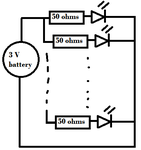
In a case say we have 3V battery and 2V LEDs. Connecting it directly would mean burning the LEDs, so I would calculate that at every rung I need a resistor to have a 1V drop. Say, I need a 20 mA through the LEDs. So, for 1V drop I need R = V/I. = 1/20mA = 50 ohms. Then, am I right in saying that I would have this:

Untitled.png

The problem I am having with this is that through every resistor, I am losing (I^2)*R = 0.02 watts. If I have say 20 rungs, that is 4 watts being wasted right?
 

Thanks, sorry for the error. Using 20 resistors or 1 resistor which is their parallel combination is another question. I want to know why we can't have LEDs connected directly if the value of the battery and the LEDs are correctly "matching". Like 3.2V battery and 3.0-3.3V LEDs.

The problem is with a battery that is say, 3V and LEDs of 1.6V. We cannot put two together in each rung because 3V is less than 3.2 (1.6 + 1.6), and at same time, if we placed just one LED at each rung, we would have to drop voltage of 1.4V (which is nearly half) through resistor. So, how can we do away with such wastage of energy with simple yet good design?

We can increase the DC voltage (by converter) to value like 4V and then, we will only be wasting 0.8V (4 - 3.2) in every rung. But is there method without DC converter? What would you suggest in this case (of 3V battery and 1.6V LEDs) for efficient and simple design?

Thank you all for your help.
 
Last edited:

I want to know why we can't have LEDs connected directly if the value of the battery and the LEDs are correctly "matching". Like 3.2V battery and 3.0-3.3V LEDs.
It might work if you're lucky, but there's a catch:
The "3.0-3.3V" part of the LED spec does not mean that all of those LEDs will work with anything from 3.0V to 3.3V. It means the required voltage for each LED is somewhere between 3.0V and 3.3V (for the rated current). One might need 3.1V and another may need 3.25V. So if they are all connected to the same voltage, they may draw different currents and glow with different brightnesses.


What would you suggest in this case (of 3V battery and 1.6V LEDs) for efficient and simple design?
For a big voltage mismatch like that, there isn't a solution that is simple and efficient.

One good approach is to use strings of LEDs with a higher voltage supply and a resistor. e.g. Use 5 of the 1.6V LEDs connected in series to get a total of 8V diode drop. Now use that with a 10V supply, so there is 2V across the resistor, giving an efficiency of 80%.
 
  • Like
Reactions: Jay_

    Jay_

    Points: 2
    Helpful Answer Positive Rating
It might work if you're lucky, but there's a catch:
The "3.0-3.3V" part of the LED spec does not mean that all of those LEDs will work with anything from 3.0V to 3.3V. It means the required voltage for each LED is somewhere between 3.0V and 3.3V (for the rated current). One might need 3.1V and another may need 3.25V. So if they are all connected to the same voltage, they may draw different currents and glow with different brightnesses..

Thanks! Important you mentioned that.

In the second case, I assume that we have a single battery. I guess using an efficient DC-DC converter is the best option then? Let me know, before I mark as solved.

Thanks :)
 

Whether you "hide" your current limiting method inside your power supply, or connect it externally, the answer is the same. Some of that power will get "wasted". Even if you directly match the diode combination directly to your battery, the battery's internal resistance will soon increase (as the battery drains) and provide your current limit.

You have to provide a means to limit the current through a diode. And a series resistor is just the simplist & cheapest way.

Trying to "match" a voltage supply output to a diode's voltage specification will NOT WORK. The I-V curve of a diode is a sharp exponential one, and there are too many small variations which you CANNOT design for or control using your techniques.

The brightness of your LED's is a function of the current passing through, since the voltage stays almost constant.
Hence, if you are concerned with power wastage in the limiting resistor, then the best alternative is to use a lossless method of current control -- and there are many switched mode constant current circuits that might work for you.

here are some --

**broken link removed**
http://electronicdesign.com/article/components/series-led-driver-operates-on-3-v-input6344
 

Whether you "hide" your current limiting method inside your power supply, or connect it externally, the answer is the same. Some of that power will get "wasted".

Are you telling me in short that the series resistor method is as efficient as any other method?

My problem is not with wasting (why put it in quotes as "wasting"?) energy, its about dissipating nearly HALF the voltage on the resistor (and thus wasting LOT of energy). Its about how much is wasted. In my example of the 3V battery and 1.6V rated LEDs, I will drop 1.4V which is large amount. I am not saying no energy has to be wasted (that would be impossible), I am just looking for more efficient (yet as simple as possible) methods.

and there are many switched mode constant current circuits that might work for you.

here are some --

**broken link removed**
http://electronicdesign.com/article/components/series-led-driver-operates-on-3-v-input6344

Thanks for these links, I haven't any knowledge on designing switching regulators, which is what the second link mentions. The first link uses a chip. I would prefer to have a transistorized design, rather than use chips. I am looking for the simplest approach, but a drop of 1.4V is too high (compared to 1.6V on LED), which is why I ask the question.
 
Last edited:

I guess using an efficient DC-DC converter is the best option then?
Yes, but it should be one that gives constant current output, not constant voltage, as rohitkhanna mentioned in his post.
 

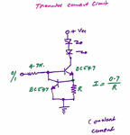
Yes, a constant current driver. Would this circuit do? current-source.png

How would I modify it for the value of current I require? Is it only dependent on R, or even on the 4.7k? Say I am driving more than 2 LEDs, and I need total current of 20mA x 20 = 0.4A. My source is say 3V.

Thanks for your help guys :)

- - - Updated - - -

p.s. note how i didn't use any quotes.. since they seem to offend you somehow. I only use them for emphasis.

Haha..thanks. I thought you were implying that waste of energy wasn't there, or was not very important when you put it in quotes.
 

Yes, a constant current driver. Would this circuit do?
Yes, but the efficiency is no better than a simple resistor. If you want high efficiency, you need to use a switch-mode supply, which is a lot more complicated.
 

So what will be the best approach in all for simple SMPS with constant current?
 

My reply in post #5 ahs a MAJOR ERROR because I did not thoroughly read it before & after posting!!!

My reference to a resistor SHOULD HAVE BEEN A RESISTOR IS AN INEXPENSIVE WAY not an expensive way to provide current limitations. I am apologize for this typo.

Foggy
 

Right. The resistor as current limiter doesn't take care of the constant current. But I guess I could go with it still? If I am using resistors, I plan to use the resistors in parallel with each other instead of a single resistor because power will be distributed in using many resistors instead of it all being concentrated at one.

So in this case (1.4 V dissipation through resistor, and 1.6V LED in each rung) how much battery power will I be wasting, or how efficient would this be?
 

if you just want to use 2 leds instead of an led +resistor ,, the current will be large, so the energy would be more wasted in comparison with using resistor which controles the current, so it would be more economized if you use LED+resistor!
 

Status
Not open for further replies.

Part and Inventory Search

Welcome to EDABoard.com

Sponsor

Back
Top