Continue to Site

Welcome to EDAboard.com

Welcome to our site! EDAboard.com is an international Electronics Discussion Forum focused on EDA software, circuits, schematics, books, theory, papers, asic, pld, 8051, DSP, Network, RF, Analog Design, PCB, Service Manuals... and a whole lot more! To participate you need to register. Registration is free. Click here to register now.

ir2110 bootstrap problem in ltspice

TuralH

Junior Member level 2
Joined
Nov 18, 2024
Messages
21
Helped
0
Reputation
0
Reaction score
0
Trophy points
1
Visit site
Activity points
110
Hi everyone,
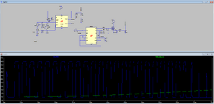
I’m working on assembling a DC-DC converter using the UC3843 in voltage PWM mode. I am using the IR2110 as a high-side MOSFET driver. The goal is to step down 60V to 12V, which will then be used to control a motor.

The issue I’m encountering is as follows:

  • The circuit works correctly when the drain voltage of the MOSFET is at 30V. in LTSpice
  • However, when I increase the drain voltage to 60V, the circuit stops working in simulation.
From the virtual oscilloscope, I noticed that:

  • At 30V drain voltage and 12V VCC, the gate voltage (HO) appears to be 42V.
  • When the drain voltage is increased to 60V, the circuit no longer operates properly.
I’m unsure why this is happening and how to resolve it. Could this be related to the IR2110 driver, the bootstrap circuit, or the MOSFET itself? I’d appreciate any insights or suggestions to help resolve this issue also about 12 volts for VCC I do it with the help of xl7005 where this step down can reduce from 80v to 12v but the consumed current is 700mA maximum. For controlling DC motor i need about 4-8A and is it possible to control this circuit with a DC motor? has anyone tried to build a buck converter using gate driver ir2110?
 

Attachments

  • Screenshot 2024-12-17 171646.png
    Screenshot 2024-12-17 171646.png
    50.6 KB · Views: 16
Last edited:
Posting simulation files (as .zip file) would others allow to debug your circuit.

General problem is that bootstrap driver doesn't work reliably for asynchronous (transistor-diode) switchers, because it depends on switcher node swinging to ground to recharge bootstrap capacitor. You need to enforce continuous current flow in output inductor, otherwise bootstrap operation may stop.
 
Hi,

I guess that gate drive circuit problems are one of the most often discussed topics here.
Thousands.
And 90% of the problems is caused by one of three problems/mistakes.

So we have many threads with many solutions and many discussions for the same problem.
--> Here: the charging path for the bootstrap capacitor.

But no ones seems to read the threads, nor the datasheets, nor the according application notes.

In the previous thread i wrote this: https://www.edaboard.com/threads/mc34063-dc-dc-buck-converter.413353/post-1785605
90% applies here, too. (1N4148, signal path, debugging, using a scope....)

Klaus
 

LaTeX Commands Quick-Menu:

Similar threads

Part and Inventory Search

Welcome to EDABoard.com

Sponsor

Back
Top