Continue to Site

Welcome to EDAboard.com

Welcome to our site! EDAboard.com is an international Electronics Discussion Forum focused on EDA software, circuits, schematics, books, theory, papers, asic, pld, 8051, DSP, Network, RF, Analog Design, PCB, Service Manuals... and a whole lot more! To participate you need to register. Registration is free. Click here to register now.

IR2104, Full H-bridge SPWM using Arduino

imranahmed

Advanced Member level 3
Joined
Dec 4, 2011
Messages
820
Helped
3
Reputation
6
Reaction score
3
Trophy points
1,298
Location
Karachi,Pakistan
Activity points
6,510
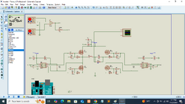
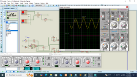
Hi, I making SPWM inverter using Arduino, IR2104 and Full H-bridge, it is giving good output but output have ripples or SPWM component, please let me know why it is appearing in output and how to rectify?. In the mean time, I am using wave generator to generate SPWM signals.

Switching Frequency = 20kHz
Fundamental Frequency = 50Hz
Cutt-off Frequency = 1591.5 Hz
 

Attachments

  • inverter.png
    inverter.png
    219.9 KB · Views: 15
  • inverter2.png
    inverter2.png
    133.5 KB · Views: 14
Hi,

if I wanted to see what happens ... I´d surely have a look at the PWM signals.. along with the sine.
You have a scopoe - so use it.

Klaus
 
Hi,

.. along with the sine.
.. no sine here.

You have chosen to show the bridge outputs... My bad, I wasn´t clear about it, but I meant the bridge inputs. Anyways you can see that it stalls.
--> So correct your SPWM generation to overcome this problem.

***
But I´ve just recognized a different problem.
What you showed in post#1 scope picture is NOT the output you wanted to show/see.

the load is the resistor --> thus you need to show the voltage across the resistor.
And since the resistor is not connected to GND you need to measure the voltage in differential mode: V_right_leg - V_left_leg

I´m not familiar with your simulation tool ... but I expect the scope to be able to show differential signals.

Klaus
 
Hi,


.. no sine here.

You have chosen to show the bridge outputs... My bad, I wasn´t clear about it, but I meant the bridge inputs. Anyways you can see that it stalls.
--> So correct your SPWM generation to overcome this problem.
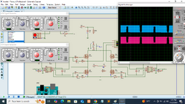
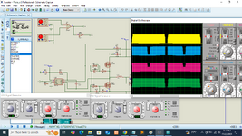
Now, I attach 4 inputs of H-bridge waveform, please see.
***
But I´ve just recognized a different problem.
What you showed in post#1 scope picture is NOT the output you wanted to show/see.

the load is the resistor --> thus you need to show the voltage across the resistor.
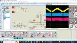
I connected scope on center point of LC filter means, after Inductor and across Capacitor, is it not?
OR how to show voltage across resistor.
And since the resistor is not connected to GND you need to measure the voltage in differential mode: V_right_leg - V_left_leg

I´m not familiar with your simulation tool ... but I expect the scope to be able to show differential signals.
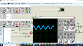
WOW!!! When I measured across Resistor so it will be sine wave WOW please find in attachment.
 

Attachments

  • 1732284900013.png
    1732284900013.png
    255.4 KB · Views: 7
  • inverter.png
    inverter.png
    250.9 KB · Views: 8

LaTeX Commands Quick-Menu:

Part and Inventory Search

Welcome to EDABoard.com

Sponsor

Back
Top