Continue to Site

Welcome to EDAboard.com

Welcome to our site! EDAboard.com is an international Electronics Discussion Forum focused on EDA software, circuits, schematics, books, theory, papers, asic, pld, 8051, DSP, Network, RF, Analog Design, PCB, Service Manuals... and a whole lot more! To participate you need to register. Registration is free. Click here to register now.

[SOLVED] inverter 12vdc - 220 vac (problem)

Status
Not open for further replies.

erchiu

Member level 5
Member level 5
Joined
Apr 7, 2012
Messages
93
Helped
2
Reputation
4
Reaction score
1
Trophy points
1,288
Location
Rome - Italy
Activity points
2,082
Hello everyone,
i have a problem with my inverter 12 vdc-220 vac (pure sine), that i use for to transform the fotovoltaic energy in to voltage for domestic use.
the energy is stored in to some the batteries.
we come to the problem.
some days ago i realized that my inverter had an malfunction.
when i turn on the main switch it not power on soon, and also after it power on, after some minutes it automatically power off.
i thought that the problem was the main switch, but when i opened the chassis, i realized that the problem was more big.
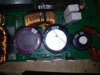
i found an capacitor exploded, an power resistor broken and an track on pcb broken and the fan is blocked.
i replaced these components, but the inverter now has another problem.
now,when i turn on, the buzzer is on and the out voltage is variable.
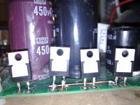
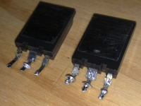
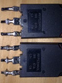
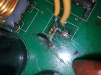
i checked visually the various componenti, and i found an mosfet that have an particolary sign.
this is an IRFPS35N50L
could be this the fault?
i have only an mosfet 2S K2746.
i know that it has the different features, but could i mount it temporally for see if change some thing
somebody, can help me with some suggestion.
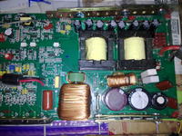
i post some photos of the pcb and the mosfet in question
thank you everyone
best regards
erchiu
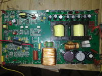
 

You must Google the inverters type number so you can see what other people have found out and hopefully get a schematic diagram. Have you a DVM, you must measure some voltages to find out which part is not functioning properly. Judging by the pictures you have a 12 V to 400 V DC-DC converter (4 diodes would turn the 400 V squarewave into DC). Then you have some sort of 400V to 220 V AC converter. Can you find your 400V?
Frank
 

hi frank,
thank you for your help.

i tried on web the type of my inverter (power jack PI-1200-1 but i not found anything.

this morning i mounted again the mosfets that i removed yesterday and now the inverter have a new behaviour.

now when i turn on it (without load), i found 220 vac in output, but after some minutes there is a smell of overheated and think that comes from the power resistors that i replaced.

if i connect also a small load, as a lamp to 15 w, after several seconds, i see the smoke that comes from the resistors in question.

now the voltage is constant also with this little load. i not connected loads more biggest.

the resistors (two) that i mounted are from 1k ohm and 5w, while the original resistor (only one) was from 470 ohm and 10w. i connected they in parallel mode. maybe i was wrong to doing so?

however, i did the measurement that you suggested me.

after the four diode,on the capacitors i found an voltage of 350 volts about.

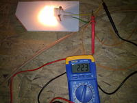
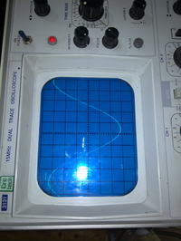
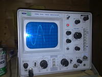
i checked the sine wave in output with my oscilloscope and it is perfect as show the pictures

could be these resistors the fault?
thank you everyone
for any help
best regards
erchiu
 
hi everyone,
Somebody know, because without load the inverter operate ok, while with also a small load (15w) the power resistors begin to smoke.
Thank you
Erchiu
 

today, i replaced the two power resistors with an only resistors from 470 ohm / 7w and after some seconds it is broken.
however the inverter has continued to work.
i did this test always with a small load (15w).
my question is:
what good is this resistance?
i can avoid installing it?
thank you everyone
regards
erchiu
 

Although you replaced the resistors, it sounds as though they are still exposed to overmuch current.

There may be more components you need to replace.

You've reached some success by bringing it back to this much degree of operation. That is a big accomplishment.

However you are finding that each step of progress can bring other problems.

Perhaps there is a first cause that still needs to be fixed? The component that started the first breakdown? Did you diagnose that? It is not necessarily a component that failed. It may be a component which has become out-of-spec. Maybe you did not replace it. It may be difficult to diagnose.

- - - Updated - - -

Although you replaced the resistors, it sounds as though they are still exposed to overmuch current.

There may be more components you need to replace.

You've reached some success by bringing it back to this much degree of operation. That is a big accomplishment.

However you are finding that each step of progress can bring other problems.

Perhaps there is a first cause that still needs to be fixed? The component that started the first breakdown? Did you diagnose that? It is not necessarily a component that failed. It may be a component which has become out-of-spec. Maybe you did not replace it. It may be difficult to diagnose.
 

Hello Erchiu,

What kind of current sensor is used in the circuit?
 

thank you braththerad and pferenc,
the first fault that i found was:

1) the fan blocked (i think from the dust)

2) an big capacitor (470uf 450v explose) that i replaced with other two capacitors (one from 330uf and one from 150uf , both from 400v), in the picture what i have replacead are black colour, while what of purple colour is also the original.

3) the power resistor from 470 ohm 10 watt broken, that i replaced to begin with two resistors from 1kohm and 5watt mounted in parallel way (but it smoked also with a small load)

4) one track broken near to the four diodes

5) one of the diodes have one pin almost fused

i removed the all the four big diodes and i checked each of them. (U8100E)
i don't know if it correct, but i checked them with an battery, led and resistor and it is lit on only one direction.

maybe must checked these diode in other way?

maybe must to replace these diodes because one of them have an pin almost fused?

i replaced only one big capacitor, maybe must to replace also the other?

i don't know which current sensor type use this inverter, where can find it, near that other components?

Thank you all for any help that i can be used to solve the problem

regards and good sunday
erchiu
 

The resistor wattages seem big, no power designer likes to waste power so they they must be required to soak up some unwanted power that gets in the way or puts an over volt situation on some transistor, or even on the output line. I suspect thatb there is meant to be a capacitor in series with the resistors, so higher frequencies end up in the resistors and not on the output line. Now if that capacitor went short circuit, the resistors would have the full line voltage across them and not just the higher harmonics. Can you check the track and see if such a capacitor is there (in series with the resistor)and is it short cirtcuit?
Frank
 

7347122900_1394999307.jpg


At least one FET has a clear sign of burning.
 

thank you frank and alertlinks,
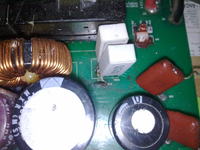
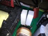
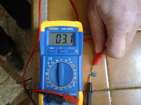
i checked the tracks near the power resistors and i found an small capacitor.
i removed it and i measured its value.
it is measure few ohm, then i can think that it is on short circuit.
on this capacitor there is not the label for identify it.
i post some photos so, you can see

thank you everyone
are you giving me a great help
 

Replace it with 103/600V or similar. You can test your load without it and the 470-ohm resistor.
 

i replaced the small capacitor near the power resistor and i tried the inverter always with same load (15w)
resistance has now stopped smoking.
now i must to mount the pcb on the chassis and to try with an biggest load
Thanks to all for the help you have given me.
best regards
erchiu
 

    Smagaso

    Points: 2
    Helpful Answer Positive Rating
Status
Not open for further replies.

Similar threads

Part and Inventory Search

Welcome to EDABoard.com

Sponsor

Back
Top