wavelet1208
Member level 2
1.What is LED matrix display?
The wikipedia said:
An LED matrix or LED display is a large, low-resolution form of dot matrix display, useful both for industrial and commercial information displays as well as for hobbyist human–machine interfaces. It consists of a 2-D matrix of LEDs with their cathodes joined in rows and their anodes joined in columns (or vice versa). By controlling the flow of electricity through each row and column pair it is possible to control each LED individually. By scanning across rows, quickly flashing the LEDs on and off, it is possible to create characters or pictures to display information to the user.
[1] By varying the pulse rate per LED, the display can approximate levels of brightness. Multi-colored LEDs or RGB-colored LEDs permit use as a full-color image display. The refresh rate is typically fast enough to prevent the human eye from detecting the flicker.
2.Feature
Long life,low cost,high brightness,less failure,view big,visible from far away and so on. But need more power consumption.
3.Where you can used?
Most of use it to advertise or signal/status.you can find it from the building outer walls,shop's door,the counter,the bus,taxi.even the name badge and so on.so,you can use it to anywhere if you wanted to show something.
4.How does led matrix work?
Let me see Mika Tuupola's introduction:
In a matrix format LEDs are arranged in rows and columns. You can also think of them as y and x coordinates. Lets assume we have 4×4 matrix. Rows would be marked from A to D and columns from 1 to 4. Now we can address each LED by row and column. Top left led would be (A,1). Bottom down led would be (D,4).
Led matrices come in two flavors. Common-row anode (left) and common-row cathode (right).
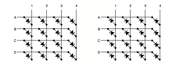
Figure above shows the different configurations. The difference between these two configurations is how you lit a led. With common-row anode current sources (positive voltage) are attached to rows A..D and currents sinks (negative voltage, ground) to columns 1..4. With common-row cathode current sinks are attached to rows A..D and currents sources to columns 1..4.
For example. To light bottom down led (D,4) of common cathode matrix you would feed positive voltage to column 4 and connect row D to ground. For sake of clarity I will using common-row cathode in examples for the rest of this article.
5.About the display component.
Usually,the matrix display contain display module,control(driver) module,power module, single cable,communication cable,and the housing.
Next i will share or find more data about LED matrix display if anyone is interested
The wikipedia said:
An LED matrix or LED display is a large, low-resolution form of dot matrix display, useful both for industrial and commercial information displays as well as for hobbyist human–machine interfaces. It consists of a 2-D matrix of LEDs with their cathodes joined in rows and their anodes joined in columns (or vice versa). By controlling the flow of electricity through each row and column pair it is possible to control each LED individually. By scanning across rows, quickly flashing the LEDs on and off, it is possible to create characters or pictures to display information to the user.
[1] By varying the pulse rate per LED, the display can approximate levels of brightness. Multi-colored LEDs or RGB-colored LEDs permit use as a full-color image display. The refresh rate is typically fast enough to prevent the human eye from detecting the flicker.
2.Feature
Long life,low cost,high brightness,less failure,view big,visible from far away and so on. But need more power consumption.
3.Where you can used?
Most of use it to advertise or signal/status.you can find it from the building outer walls,shop's door,the counter,the bus,taxi.even the name badge and so on.so,you can use it to anywhere if you wanted to show something.
4.How does led matrix work?
Let me see Mika Tuupola's introduction:
In a matrix format LEDs are arranged in rows and columns. You can also think of them as y and x coordinates. Lets assume we have 4×4 matrix. Rows would be marked from A to D and columns from 1 to 4. Now we can address each LED by row and column. Top left led would be (A,1). Bottom down led would be (D,4).
Led matrices come in two flavors. Common-row anode (left) and common-row cathode (right).
Figure above shows the different configurations. The difference between these two configurations is how you lit a led. With common-row anode current sources (positive voltage) are attached to rows A..D and currents sinks (negative voltage, ground) to columns 1..4. With common-row cathode current sinks are attached to rows A..D and currents sources to columns 1..4.
For example. To light bottom down led (D,4) of common cathode matrix you would feed positive voltage to column 4 and connect row D to ground. For sake of clarity I will using common-row cathode in examples for the rest of this article.
5.About the display component.
Usually,the matrix display contain display module,control(driver) module,power module, single cable,communication cable,and the housing.
Next i will share or find more data about LED matrix display if anyone is interested
")