ZacMan
Newbie level 4

G'day all. I'm working on a wee project to interface with the network in my Toyota Altezza (very similar to a Lexus IS300) The vehicle uses 3 distinct networks, but the one I'm interested in is the BEAN (Body Electronic Area Network). I've repowered the vehicle with another motor, and would like to get my coolant temperature gauge operating correctly. The instrument cluster pulls the data for this off the BEAN network, but as I'm no longer running the original engine management computer, this data is no longer available!
I've deciphered the network message structure, and have isolated the messages I have to send and how to construct them. I've done a couple of proof on concept tests with an arduino, bit banging my constructed messages to the instrument cluster on the bench, and it works insofar as I can observe the gauge move to the correct position.
The last couple of tricky tasks are programming a software CDMA/CD algorithm, and the correct hardware interface to the network.
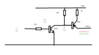
The physical layer of the network is a single wire bus, with a 0-10v 10kbps signal. The tricky parts that is stumping me, is that the bus idles low, so all my ideas for transmitting on the bus using an open drain with pull-up system destroy the bus signal whenever my arduino is not communicating.
Can anyone point me in the direction of an idea, or some reading to help me figure out how to interface to this bus? Basically, I need to level shift my 5v signal from the arduino, to the 10v signal the bus needs, and not destroy all the other communication on the bus at the same time.
Cheers for any help you can offer .
.
I've deciphered the network message structure, and have isolated the messages I have to send and how to construct them. I've done a couple of proof on concept tests with an arduino, bit banging my constructed messages to the instrument cluster on the bench, and it works insofar as I can observe the gauge move to the correct position.
The last couple of tricky tasks are programming a software CDMA/CD algorithm, and the correct hardware interface to the network.
The physical layer of the network is a single wire bus, with a 0-10v 10kbps signal. The tricky parts that is stumping me, is that the bus idles low, so all my ideas for transmitting on the bus using an open drain with pull-up system destroy the bus signal whenever my arduino is not communicating.
Can anyone point me in the direction of an idea, or some reading to help me figure out how to interface to this bus? Basically, I need to level shift my 5v signal from the arduino, to the 10v signal the bus needs, and not destroy all the other communication on the bus at the same time.
Cheers for any help you can offer

