Continue to Site

Welcome to EDAboard.com

Welcome to our site! EDAboard.com is an international Electronics Discussion Forum focused on EDA software, circuits, schematics, books, theory, papers, asic, pld, 8051, DSP, Network, RF, Analog Design, PCB, Service Manuals... and a whole lot more! To participate you need to register. Registration is free. Click here to register now.

Interfacing Stm32f1 with GSM

Status
Not open for further replies.

Nihaludeen

Member level 2
Member level 2
Joined
Oct 29, 2017
Messages
46
Helped
0
Reputation
0
Reaction score
0
Trophy points
6
Activity points
460
Hi friends, I am trying to interface GSM with my ARM controller [stm32f103c8t6].

I knew a little about the working of GSM,
- By sending the "AT" command to GSM, it will respond with a "OK" message.

Before interfacing GSM with arm, i learned how to use HAL_uart function (generated from cube MX). I tried to transmit and receive data to "arm and terminal(pc)" , and it works good in HAL_uart function.
Problem:
- But when i connect to GSM with ARM, No response is getting from GSM.
- I tried another method, i use uart max232 with GSM to transmit and receive data it works fine. [sending data to pc terminal via max232].

I attached the uart communication diagram arm,gsm and max232.(I use max232 to communicate with pc since i have only st-link v2 which has no tx and rx).
Also the code generated from cube mx.
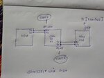

IMG_20181123_122329.jpgIMG_20181123_122329.jpg
 

Attachments

  • stm32f1 with gsm.txt
    8.1 KB · Views: 92

Hi,

Check:
* what needs to be done prior to "AT" command communication. Maybe some special button press, timing after power up...
* voltage levels at UART lines. V_OH, V_OL at transmitter with V_IH, V_IL at receiver.
* UART settings. Baud rate, parameters like "8N1"...

Klaus
 
Hi,

Check:
* what needs to be done prior to "AT" command communication. Maybe some special button press, timing after power up...
* voltage levels at UART lines. V_OH, V_OL at transmitter with V_IH, V_IL at receiver.
* UART settings. Baud rate, parameters like "8N1"...

Klaus

I checked the first and third points, which was correct in my circuit friend.
I need to check the voltage at gsm and arm [tx and rx] line.

- - - Updated - - -

Each string should end up with '\r\n\' (0x1310) code.

I have tried but doesn't getting correct response.
I am getting Only 'A' as a response from GSM.

- - - Updated - - -

Hi,

Check:
* what needs to be done prior to "AT" command communication. Maybe some special button press, timing after power up...
* voltage levels at UART lines. V_OH, V_OL at transmitter with V_IH, V_IL at receiver.
* UART settings. Baud rate, parameters like "8N1"...

Klaus
Without interfacing GSM with ARM...,
Gsm tx volt= 2.8v rx volt= 2.8v
arm tx volt= 3.3v rx volt= 0v

while interfacing GSM with ARM...,
In arm tx rx...
Tx volt= 3.3v rx volt = 2.8v

I convert that 3.3v [tx of arm] to 2.8v by voltage divider. But no use.
I getting 'A' as a response, instead of 'OK'.
 

Hi,

Without interfacing GSM with ARM...,
Gsm tx volt= 2.8v rx volt= 2.8v
arm tx volt= 3.3v rx volt= 0v

while interfacing GSM with ARM...,
In arm tx rx...
Tx volt= 3.3v rx volt = 2.8v
I assume you mix "supply voltage" with "logic signal voltage" levels.

V_OH, V_OL at transmitter and V_IH, V_IL at receiver should be specified in the according datasheets.

****
Did you verify the expected levels with the use of a scope?

Klaus
 

Hi,


I assume you mix "supply voltage" with "logic signal voltage" levels.

V_OH, V_OL at transmitter and V_IH, V_IL at receiver should be specified in the according datasheets.

****
Did you verify the expected levels with the use of a scope?

Klaus
V_OH, V_OL at transmitter and V_IH, V_IL at receiver GSM should not increase 2.8 v.
So i reduced the transmitter of the arm by 2.8 v [1 K and 5.7 K resistor as voltage divider] as specified in the GSM datasheet.
Datasheet [ pg : 26 ] : https://www.elecrow.com/download/SIM800C_Hardware_Design_V1.02.pdf

But When i connect GSM with max232 [uart]. It works fine.., By sending "AT" command from max232 to GSM, I am getting response to max232 as "OK" [In terminal].
The problem occur only when i replace my max 232 with arm. Arm receives "A" as a response from GSM.
 

Hi,

V_OH, V_OL at transmitter and V_IH, V_IL at receiver GSM should not increase 2.8 v.
Where is this information from?
Table 9 of the given datasheet = page 25 says specifies other values.

Anyways:
The resistor dividers should work.

What about the scope picture.
Are the levels as expected?
Is the timing as expected?

Klaus
 
Thank you for the response, the problem was solved almost..,
I use the interrupt for uart receive , now i am getting the response as "OK" from GSM.
But i am having a small problem in that, the received response i saved in the single variable which is a circular buffer.
For example:
uint8_t rx[10]; <-----receiving variable
- first response is "OK"
- second response is "Cpin ready"
- when i print my rx[10]........I get output as "OK Cpin ready"

But i want to overwrite the response in my rx[]
 

Hi,

I wonder....how did you test it?
I doubt you tested with the code if post#1.

Btw: how can "OK Cpin ready" fit into a 10 byte wide array? And I'm missing the line delimiters...

Klaus
 

No friend, i have changed the code slightly as i mentioned above(i use interrupt) and changed rx[] size.

I getting a small problem,
- Whenever i transmit to GSM as "AT", GSM will respond to arm as"OK" which will be stored in rx[] (since i used interrupt).
That is, rx[0-1] will have "OK"
- And when i transmit to GSM as "AT+CPIN?", GSM will respond to arm as "+CREG: 0,0 OK"
Now rx[2-14] has "+CREG: 0,0 OK"

But i want to start again from rx[0] for next response, how to overcome this.
By clearing buffer,emptying string ?????
 

Attachments

  • GSM edited code.txt
    8.2 KB · Views: 65

Hi,

Before you write the second command you should read Rx. The Rx_function should correct the read_pointer.
Then start the second command.
Then read the second response.

With a circular bufferyou have two pointers: read_pointer and write_pointer.
The read_function does not always start to read at rx(0). It starts to read at the read_pointer position.
At the vedy beginning it starts at 0.(OK)
At the next read it starts at 2.

Klaus
 

Status
Not open for further replies.

Part and Inventory Search

Welcome to EDABoard.com

Sponsor

Back
Top