Continue to Site

Welcome to EDAboard.com

Welcome to our site! EDAboard.com is an international Electronics Discussion Forum focused on EDA software, circuits, schematics, books, theory, papers, asic, pld, 8051, DSP, Network, RF, Analog Design, PCB, Service Manuals... and a whole lot more! To participate you need to register. Registration is free. Click here to register now.

Interfacing multiple i2c devices from PIC MCU

Status
Not open for further replies.

Vibrant2020

Newbie level 6
Newbie level 6
Joined
Sep 23, 2020
Messages
13
Helped
0
Reputation
0
Reaction score
0
Trophy points
1
Activity points
155
Hi,

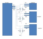
I am accessing 3 i2c devices from my PIC MCU.

I2C devices are:
1. EEPROM
2. PCF8574T Module 1
3. PCF8574T Module 2

I pulled up the SCL and SDA line of the EEPROM to VCC through 4K7 resistor. The 2 modules of PCF8574T (bought from online store) have their own pull up resistors of the value 1K on each SCL & SDA line. I can able to access and get the results without any problem as of now. But I want to know shall I continue with these resistors or should I remove the resistors from the module and should I use only one resistor for SCL and SDA line for whole I2C devices?

picture attached for your reference.

thanks in advance.
Vibrant
 

Attachments

  • PIC_AND_MULTIPLE_I2C_DEVICES.JPG
    PIC_AND_MULTIPLE_I2C_DEVICES.JPG
    42.1 KB · Views: 159

It is unusual t have 1K pull-up resistors on modules, usually they are 4.7K.
The limitation is whether the devices can pull the SDA and SCL lines low enough when more current can flow. If they are 4.7K I wouldn't worry, leave them in. If they really are 1K and three are in parallel it gets worryingly close to maximum current ratings so I would remove at least one set of resistors. Electrically, as long as pull-ups exist somewhere on the lines it should work.

Brian.
 

Hi,.

I recommend to read through I2C specification.
We professionals do this, too.
No need to read through all, but at least the index and some sections you find useful for your design.

There is a section that describes the hardware including pull up.

Just some raw information:
It depends on a lot of things. Bus length, bus capacitance, bus voltage, devices on bus, SCL clock frequency, driving capabilities on the bus...

So for short busses a single pullup on each line with value of 10k down to 1k should work. With 1k you should be on the safe side.

Using 4k7 || 1k || 1k causes a lot of current (depends on VCC which is unknown).
If your master can drive this current
* without being overloaded and
* while maintaining valid LOW levels
everything is O.K.

So for high speed and long busses you need low resistance.
For low speed, short busses, long battery life, good LOW levels one will consider high resistance.

Klaus
 

It is unusual t have 1K pull-up resistors on modules, usually they are 4.7K.
Yes indeed. But I checked the markings on the resistors. It shows as 102 (1 K) on both the modules.

If they really are 1K and three are in parallel
Two 1K and One 4.7K are in parallel.

Electrically, as long as pull-ups exist somewhere on the lines it should work.
Using 4k7 || 1k || 1k causes a lot of current (depends on VCC which is unknown).

VCC is +3.30V (PIC and all i2c devices), Thermal Printer 12V/2A TTL serial interface from the PIC MCU.

So, for safer side it is better to remove the 1K resistors from both the modules and uses 4.7K resistors on SCL & SDA lines as common to all three i2c devices. Shall I?

For low speed, short busses, long battery life, good LOW levels one will consider high resistance.
i2c SCL Clock = 400 KHz

thank you.
vibrant
 

This is a marginal case, meaning you are asking a GPIO tro sink ~ 6 mA to meet
logic low level on the 3V buss. Which, depending on part you are using would,
by todays standard, be a light load = no issue with noise margin. The other
consideration in todays processors is total port allowed current, if your part splits its
port supply out by individual port. Or just plain old total chip Vdd current. Again I
suspect not an issue unless you have large loads on other pins as of yet undisclosed.

So in short only good reason to eliminate the 1 Ks is power, and cost. So yes remove them
unless your buss loading has a lot of C on it, and speed caclulations indicate. Seems from
your post this is not case.


Regards, Dana.
 

Status
Not open for further replies.

Similar threads

Part and Inventory Search

Welcome to EDABoard.com

Sponsor

Back
Top