Continue to Site

Welcome to EDAboard.com

Welcome to our site! EDAboard.com is an international Electronics Discussion Forum focused on EDA software, circuits, schematics, books, theory, papers, asic, pld, 8051, DSP, Network, RF, Analog Design, PCB, Service Manuals... and a whole lot more! To participate you need to register. Registration is free. Click here to register now.

Infrared RX TX not working with high speed objects

Status
Not open for further replies.

3dprintingtech

Newbie level 5
Newbie level 5
Joined
Mar 8, 2015
Messages
9
Helped
0
Reputation
0
Reaction score
0
Trophy points
1
Activity points
73
Now I'm no electronic wizard so bear with me.
I have mad a small circuit designed to detect when a BB gun is firing and flash a small led on the side of the BB gun to let you know its firing (and still have ammo).
I used these RX and TX led's from maplin as a detection (CH11M, CH10L) the signal goes through a 74HCT14N HCT CMOS then a 2n3906 transistor.

The Problem being: When a BB is dropped through the detector the led flashes (i have also flicked them to make it move a little quicker) so I thought it was all working. When I fire a BB at aprox 330 feet per second it does not detect it and the led does not flash.
it would appear that the rx and tx led does not detect fast enough.
now the BB is 6mm Dia and can travel at a max of 500FPS or 152.4 m/s.

I think the optics need changing but im not sure what maths is required or what I need to look at.

Any pointers please all.

(below is my circuit layout)
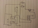
20150312_005419.jpg
 

hi,
Check the response time of the photo detector.
If you have a datasheet for the CH11 please post or link to it so that we can check it out.
 

You need some more resistors in there!

One (suggest 4.7K) between the 7414 and the base of the transistor.
One (suggest 100 Ohms) between the collector of the transistor and the LEDs.

Try increasing the 100 Ohms at the opto LED to 220 Ohms, at the moment the current is probably too high.
Drop the 22K down to 10K to increase the response speed of the detector.

Your biggest problem is how long the LED lights when the beam is interupted. You really need a pulse stretcher so the minimum time the LED lights is increased from the transit time of the BB (very quick) to something like 1 second which is far easier to observe. It's easy to do if you use the remaining parts of the 7414.

Brian.
 
Thanks guys

Eric - There only seems to be a small amount of info on the site no data sheet and i cant see a response time.
**broken link removed**

Brian - ill add in the resistors and do a little more testing I had a 22k instead of a 10k (i started with 10k) as I found the BB would Trigger the but the signal would not go low enough to turn it off after trial and error i found the higher resistor turned the led off again. but ill go back to a 10k with your other suggestions and see how I get on.

Had a look at the pulse stretcher but im slightly unsure what capacitor or resistor I would would need Any advice?
the circuit i saw is last page of here https://www.fairchildsemi.com/application-notes/AN/AN-140.pdf

Thanks all

Max
 

Typically that kind of detector has a rise and fall time < 10uS so that should't be a problem.

The values depend upon how long you want the LED to flash. I've attached an image of how I would do it, it works slightly differently to the application note because your incoming pulse is the other way up to theirs. Your sensor is conducting until the beam is broken, they assume the opposite. To make the flash longer you can increase the value of the resistor or the capacitor but with the 7414 you may find the timing less predictable and it may stop working with higher values.

I strongly suggest you use the 74C14 if possible rather than the very old 7414 device but both will work.

Brian.
stretcher.jpg
 
I might have to go back to the drawing board as this isnt working. ive wiered up as per the diagram and tried a few different ways all with no luck.
i have ran the signal in to an arduino as i thought this would work to keep the led on for longer and so i can see out put on a screen this works fine until i fire the BB and then it dosnt detect again.
Im thinking what im using as optics might be the problem as every thin is pointing to that.

Thanks so far guys and if anyone has any other ideas im open to them.
 

If it is an optical problem the most likely cause is the detector being a 'TV remote' type instead of a simple IR light detector.
The RC types have circuits built in them that filter out all but a narrow range of flashing LED speeds, normally in the range of 36KHz to 38KHz. Its a method used to make them immune to background light but it also makes them useless for detecting a rapidly broken beam. Even adapting your circuit to make the LED flash wouldn't work because of the risk of the interruption 'strobing' (being missed) if the BB broke the beam when the LED was already in an off period.

You could try a different detector of course, Maplin give nothing away in their specifications and I have searched for detectors with the same physical dimensions but can't find any. It isn't by chance in a pale pink translucent package is it? Similar sized ones were commonly used as tape end detectors in VCRs.

Tell me, is the gun firing real metal BB pellets? If it is, there may be other methods to detect one passing by.

Brian.
 
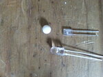
below are both the detectors i have tried and a BB for show.
both are maplin
Left is NP64U **broken link removed**
right is ch11m **broken link removed**

Maplin is rubbish on there info.

Might have to order something in via else where but at a loss as to what I even need now.
As you can see the BB is plastic its for airsoft type BB guns.

20150312_154554.jpg
 

This sheds some light on the problem (pun intended).

The sensors has a clear plastic case which will not exclude outside light and although intended for IR wavelengths they work over a much wider range of light spectrum. The ch11m is indeed the kind used in VHS VCRs where the tape mechanism drops the tape casing over a LED and the sensors look into the sides of the casing for light passing through the clear leader strips at the extreme ends of the tape. If you look at a VHS cassette you will note a deep hole in it's middle where the LED get placed and if you lift the flap up, near the hinges you will see a small hole that looks to the deep hole through the tape itself. The passage of light is used to tell the mechanism whether a tape is present and if it is fully fast forwarded or rewound. Inside the tape body it is of course shielded from room light so there is no need to protect against it.

The kind of sensor you need is one with a black body, it looks like glossy normal epoxy like the stuff used to encapsulate ICs and transistors but it blocks light except for in the IR part of the spectrum.

It is also possible, although unlikely, that the plastic BB is transparent to IR light. You can test that easily, use your TV remote control, place the BB close up and immediately in front of the LED in the remote and see if it still operates the TV. The range may be reduced but when you consider how close the LED and sensor are in the gun....

Brian.
 
ah ok thats all making a little more sense.

I have tried to keep the led in an encloses
optical holder.png
Its designed to make sure the BB is in the middle and that the LED only has a small hole to see incomming light.
works fine dropping the BB through but once its shot it doesnt detect it and even the arduino dosnt detect a signal from the sensor so i think its more of the timeing issues with the maplin ones.

would this be the right type you are referring too **broken link removed**

Thanks for the help and advice Brian.
 

That should be a good choice. Note the difference in spectral response of the clear and black bodied versions.
I do not have one here to experiment with but there is just a chance you would have to use it in photovoltaic mode with a small interface circuit, in other words make it produce a voltage when iradiated which you amplify to get the output signal.

Do you have access to an oscilloscope? It would make debugging far easier if you could see shape of the signal from the detector, assuming there is one at all.

Brian.
 

yeah just have to wait for some to arrive now probley next week now :(

dont have an oscilloscope my self but my local hackerspace does but there open night was tonight so might have to pop down next week if i need to.

I shall up date the thread once they have been changed out and some more testing is complete.
Thanks again Brian

Max
 

Status
Not open for further replies.

Part and Inventory Search

Welcome to EDABoard.com

Sponsor

Back
Top