Continue to Site

Welcome to EDAboard.com

Welcome to our site! EDAboard.com is an international Electronics Discussion Forum focused on EDA software, circuits, schematics, books, theory, papers, asic, pld, 8051, DSP, Network, RF, Analog Design, PCB, Service Manuals... and a whole lot more! To participate you need to register. Registration is free. Click here to register now.

Infra Red Proximity sensor and Sunlight Problem

Status
Not open for further replies.

userx2

Full Member level 3
Full Member level 3
Joined
Sep 19, 2008
Messages
177
Helped
2
Reputation
4
Reaction score
3
Trophy points
1,298
Activity points
3,092
Hello,

I am working on a sensor to detect an object at around 1-2" (25-50mm)

I do it by pulsing the IR LED and checking for a difference on the received ADC values in the receiver/Optotransistor.

With no object, there is little to no difference in the off/on values.
When a reflection occurs from an object, there is a larger difference which I then detect.

Problem is in strong sunlight.
I cannot get it to detect any noticeable on/off difference when the object is present.

Basically, the sunlight is so strong that it just also seems to reflect from the object and into the sensor as if it was not present and still drown out the sensor pulses.

Does anyone have any suggestions for how I can improve this perhaps?

Best regards
X
 

Hi,

I'd expect the AC signal not to be influenced by the DC (sunlight) signal.

Maybe your circuit is not suitable.

Klaus
 

I do it by pulsing the IR LED and checking for a difference on the received ADC values in the receiver/Optotransistor.
What rate are you pulsing it? If you are comparing two measurements, one with the LED on and one with it off, I think you will run into problems.

A better solution is to continuously pulse the LED at high frequency, at least several KHz and then use an electrical filter to pass only that frequency from the sensor. It will eliminate almost all the background light problems, including light from artificial sources. Most commercial IR proximity sensors work in the 30KHz to 60KHz range.

Brian.
 

I need to clarify...

The IR sensor has LED and phototransistor built in.
I only have a pulldown resistor on the transistor e and that goes into the micro ADC.

I do an ADC converion for LED off. Then turn the IR LED on and do another conversion.

There is no exact frequency as I have multiple sensors of this type in round robin and other stuff, interrupts etc.

The receiver is saturating in that the 10bit ADC just sits at 1023 ish, regardless if my IR is on or off.
Without sunlight I get vastly different on and off values if an object is present.

In sunlight it will work if the sensor is fully covered, not allowing stray IR to get in.

I may need a circuit that removes the DC saturation but am not sure.

- - - Updated - - -

Sensor is OPB733TR
Here is a napkin schematic...
 

Attachments

  • 20200603_195802.jpg
    20200603_195802.jpg
    311.6 KB · Views: 254
Last edited:

Hi,

for sure the voltage at the resistor is non linear with the given circuit ...
you need to calculate currents, dimensionate the parts (resistors) ... and maybe you see you need an amplifier...

The internet is your friend: do a search on "IR circuit sunlight suppression"

Klaus
 

It's a photo transistor problem in the first place. Too sensitive despite of black (solar light blocking) window. What's the present sensor load resistor value? It may be reduced to about 500 ohm.
 

The resistor is 33k. I started at 3k9 but then there is too little gain to detect the object at 2". The 33k gives a good on/off delta of around 200 on the ADC at the desired obejt range. 900 when the sensor is covered by hand comlpetely.

Yes, there is a IR transparent special window in front of the sensor.
 

Hi,

the resistor must not be defined by the "gain" for sensing the object but it must be defined by the max intensity of light ... which obviously is the sunlight.

If the signal then is too low for sensing the object you need to add an AC amplifier.


Klaus
 

I will investigate.

Do ypu think the actual comparatively weak pulses would still be present and detectable in sunlight? That would be good news.

I will try to lower the gain so the bright sunlight will not reach max outpu voltage of the circuit and the AC couple it into an amplifier.
 

The resistor is 33k. I started at 3k9 but then there is too little gain to detect the object at 2". The 33k gives a good on/off delta of around 200 on the ADC at the desired obejt range. 900 when the sensor is covered by hand comlpetely.
Doesn't make sense to me. Why do you need a delta of 200 counts? 5 or 10 should be enough for detection.

Anyway, the problem has been clarified, I think. The alternative is between a simple circuit with lower load resistance and limited sensitivity or more complex circuit with AC amplifier.
 

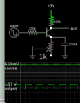
Your bias seems to be a weak AC signal riding a DC component. When you want to emphasize the AC, install a capacitor in the emitter leg. You don't need to amplify the DC portion nevertheless DC current has a path to ground through the ohmic resistance. The capacitor gives you increased gain of the AC portion.

weak AC rides bias NPN RC in emitter leg passes AC.png

The bias has sufficient DC voltage to turn on the transistor. The 40 kHz AC is only 10mV amplitude yet it's amplified about 100x by the transistor.
 

Have you put a proper shroud on the detector to exclude
sources not directly in the desired field-of-view?
 

Your bias seems to be a weak AC signal riding a DC component. When you want to emphasize the AC, install a capacitor in the emitter leg. You don't need to amplify the DC portion nevertheless DC current has a path to ground through the ohmic resistance. The capacitor gives you increased gain of the AC portion.

View attachment 159709

The bias has sufficient DC voltage to turn on the transistor. The 40 kHz AC is only 10mV amplitude yet it's amplified about 100x by the transistor.


I have built this circuit to test.

The idea is good but I am having problems with that too.

When the light becomes strong ( I use an IR emitter as test source), there is no more AC signal detectable. The collector voltage simply goes to Vcc/2.

I am suspecting the transistor may be saturating.
That would be bad as then all bets are basically off.

Perhaps the test source is not representing real sunlight.


And yes, we have a proper sensor housing which shields light form all but the wanted direction and it is covered with special IR lens material as well.

Testing continues...


Regards
X
 

When the light becomes strong ( I use an IR emitter as test source), there is no more AC signal detectable. The collector voltage simply goes to Vcc/2

Resistance adjustments need to be done delicately. The challenge is to find the right bias for the phototransistsor.

It would be easy to say 'amplify the signal with an op amp' but still the phototransistor itself needs careful attention to voltages and currents reaching it, if you wish to get the most out of it.
I replaced the resistors with 10 turn pots and experimented for several hours but all to no avail.
The sensor just can't handle it. I could not find any details on IR intensity vs base or collector current. No real further info on the phototransistor.
Due to time constraints, I have given up on doing this with discrete sensors and I am now experimenting with Vishay VCNL4020 sensors that run I2C.
So far, they work quite well in even extreme sunlight. The challenge now is to get firmware working that can talk to them.
 

Status
Not open for further replies.

Part and Inventory Search

Welcome to EDABoard.com

Sponsor

Back
Top