dick_freebird
Advanced Member level 7

Working on a test jig to take a 400V GaN power device
to the cyclotron for single event survivability and spurious
drain current testing. This voltage swing needs to be fully
exercised, but my 'scope probes say 300V, yadda yadda.
Between a resistor divider and a pulse transformer, the
divider looks cleaner if a bit slower. Transformer has the
nice property of being a non-dissipative load but what
we specifically want, may be longer lead time than
remains to the trip.
"On" power level says I need 150W resistors and some
values plus high pulsed duty will put me in wirewound.
Thick film values are very limited at this power level.
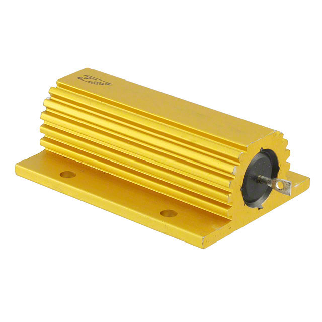
Looking specifically at TE Connectivity (looks like used
to be Ohmite?) FSC150 range.
My interest in waveform fidelity wants board C and
resistor L minimized. TE Connectivity datasheet says
"low inductance" but no quantitative info found in
the 4 pages of Google hits from "HSC150" "inductance"
"resistor". Only thing I saw was one thesis where the
MOSFET load was ringing pretty badly, and wirewound
resistors were used.
Couldn't find anything quantitative on TE Connectivity
(was Tyco Electronics) web site.
What I'm looking for, is any kind of reasonable rough
inductance value for a 1Kohm 150W like this guy (one
of the other divider values):
https://www.digikey.com/en/products/detail/te-connectivity-passive-product/HSC1003K9J/5587209
Anybody ever measure, or see a number for this
kind of wirewound?


