Continue to Site

Welcome to EDAboard.com

Welcome to our site! EDAboard.com is an international Electronics Discussion Forum focused on EDA software, circuits, schematics, books, theory, papers, asic, pld, 8051, DSP, Network, RF, Analog Design, PCB, Service Manuals... and a whole lot more! To participate you need to register. Registration is free. Click here to register now.

INDUCTANCE AND CAPACITANCE METER USING PIC...LC METER

Status
Not open for further replies.

roykyn

Full Member level 5
Full Member level 5
Joined
Sep 15, 2006
Messages
253
Helped
12
Reputation
24
Reaction score
5
Trophy points
1,298
Activity points
2,704
pic lc meter

NEED SCH PCB AND WAT NOT.....
 

lc meter

look at

h**p://www.qsl.net/iz7ath/web/02_brew/21_LCMeter01/

its works fine

regards
albert
 
  • Like
Reactions: ACHILE

    ACHILE

    Points: 2
    Helpful Answer Positive Rating
lc meter 16f628

Try this one, it uses a PIC, it is very accurate and simple.
I had built it and works fine.

Code:
http://electronics-diy.com/lc_meter.php

There are also some other projects on the above page.
 

lc meter pic

dude i know better site than those...use a google search....i have a new problem....i cannot get accurate value capacitors or inductors do u have any method to minimize the error....
 

16f628 lc meter

roykyn said:
dude i know better site than those...use a google search....i have a new problem....i cannot get accurate value capacitors or inductors do u have any method to minimize the error....

The LC meter (that uses the PIC) requires two things to be accurate.
1 a 4mhz crystal (the PIC is basically a frequency counter)
2 an accurate capacitor for calibration.

If you have access to a capacitor meter then simply hand check a few.

Some versions of the L/C meter have a frequency display to tell you the free running frequency of your tank circuit. Still you need to know at least one variable (inductor or capacitor value) to modify the software for calibration.

If you have no access to those two somewhat common parts then your L/C meter will be inaccurate and you have no way to know by how much.

You need the tools. Else your SOL.
lc_meter_PIC16F84A_2.jpg
 

pic capacitance meter

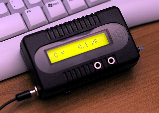
So, the beautiful picture showing a 0.1pF it's just a measurement error ?
:D
How many pF has the measuring cable connected to this capacimeter ?
 

very accurate lc meter

I've built the LC meter project, it works very well. The tank circuit is the secret.

Here's the FAQ on it. If you KNOW the inductor value you could in theroy skip the calibrate mode by storing caibration data in EEPROM.
**broken link removed**

You could not do it with a 16F84 (not enough ROM @ 1K) a 16F628A would be a better choice. They have the source for both on this site.
**broken link removed**

Here's another nifty project and it claims to do caps and inductors too.
**broken link removed**

**broken link removed**
 

inductance meter pic

blueroomelectronics guy....thank u for ur interest.....i do have a freq counter built on pic 16f72...i am using pic 16f72 for the lc meter tooo.....i am not getting the concept....i mean how the software works ....then i can write my own ....
 

pic inductance meter

blueroomelectronics,

i have built the meter described at

**broken link removed**

using PIC16F84A with good results also.

roykyn,

Mr. Rice has a good explanation on how it works. Basically, a comparator is wired to be a free running oscillator (whose frequency is a function of the capacitor or inductor to be measured).

The PIC software implements a frequency counter. Mr. Rice has the source code on the website. He measures frequency by taking the input on RA4 and configures that pin to increment TIMER0 on the falling edge. He then waits a specific time and uses the change in TIMER0 to determine the frequency, converts it to a capacitor/inductor value, and displays it on the LCD. He has equations for the conversion from frequency to component value (for the oscillator used) on the website as well.

-Jonathan
 

Re: inductance meter pic

blueroomelectronics guy....thank u for ur interest.....i do have a freq counter built on pic 16f72...i am using pic 16f72 for the lc meter tooo.....i am not getting the concept....i mean how the software works ....then i can write my own ....

sorry for bothering you, but it would be a real help for me if you can share the schematic and the hex file with me...
my email is juwel_rana82@yahoo.com
 
Re: pic inductance meter

Hi jonw0224.

Could you please, confirm Mr. Rice´s link you gave us?

**broken link removed** , it seens to be broken and i would like to visit very much.

Thanks

Simão
 

Status
Not open for further replies.

Part and Inventory Search

Welcome to EDABoard.com

Sponsor

Back
Top