Continue to Site

Welcome to EDAboard.com

Welcome to our site! EDAboard.com is an international Electronics Discussion Forum focused on EDA software, circuits, schematics, books, theory, papers, asic, pld, 8051, DSP, Network, RF, Analog Design, PCB, Service Manuals... and a whole lot more! To participate you need to register. Registration is free. Click here to register now.

Impedance matching of amplifier stages

Status
Not open for further replies.

boylesg

Advanced Member level 4
Joined
Jul 15, 2012
Messages
1,023
Helped
5
Reputation
10
Reaction score
6
Trophy points
1,318
Location
Epping, Victoria, Australia
Activity points
11,697
I have been reading about impedance matching between amplifier stages and that ideally you need the input impedance of stage n+1 to be much greater than the output impedance of stage n.

So it is an easy matter to work out the input and output impedances of a class A amplifier - TransistorAmp software does it for you.

But how do you work out the input and output imdendance of a complementary pair? I can find no websites that tell you how to do this. Is the input imedance simply the BE impedance of the transitors in the pair? And if so where do you get that sort of info from because the datasheet for BC327 for example does not specify these parameters.
 

impedance matching between amplifier stages and that ideally you need the input impedance of stage n+1 to be much greater than the output impedance of stage n.

For maximum power transfer you would want the load impedance to match the preceding stage.
It is when you want to avoid loading (distorting), that you want the load to be much greater.

But how do you work out the input and output imdendance of a complementary pair?

To calculate the impedance of a complementary pair...

1/ ( 1/R1 + 1/R2 ) )

Where R1 is the impedance of one device when on,
and R2 is impedance of the other device when off.

The opposite half of the cycle should be factored in as well.
If the impedances are not too different then you add them together and take the average.

If they are very different then there is an imbalance, and the complementary pair is not working as a complementary pair.
 

Where R1 is the impedance of one device when on,
and R2 is impedance of the other device when off.

There in lies my problem.

Where do you get these values?

Because they are not in the datasheets for the BC327/BC337 I am using as far as I can see. And googling impedance + BC327 has been fruitless.
 

I think the idea is to bias the transistors so their impedance is at the desired amount,
or so that current flows at the desired rate,
or so that voltage across the load is at the desired level.

By the way, when I wrote:
R2 is impedance of the other device when off.
I was thinking it is not necessarily all the way 'off' (which would be very high impedance), but a tiny bit 'on' during that half of the cycle (as is often the case in class AB).
 

I think the idea is to bias the transistors so their impedance is at the desired amount,
or so that current flows at the desired rate,
or so that voltage across the load is at the desired level.

By the way, when I wrote:

I was thinking it is not necessarily all the way 'off' (which would be very high impedance), but a tiny bit 'on' during that half of the cycle (as is often the case in class AB).

That is the other bit of info I have been unable to find any where.

There is plenty of info on calulcations for class A amplifier on its own, but absoluely nothing with respect to biasing a complementary pair and very little matching it class A first stage complementary pair stage.

The best I have been able to do is a website that simply stated that the second stage should have a higher impedance than the first stage in the right ratio - a real coc% tease, so to speak, if you ask me. What didn't they bother elaborating on this?

I am left with looking at examples of combines class A complementary pair amplifiers and a lot of guess work.

- - - Updated - - -

Input imedance of around 1k seems to be about right for an ipod. I tried input impedances of 40 amd 100 but it causes the resistors of the class A first stage to heat up too much.

Output impedance of 1k for the class A first stage is no good as it wont drive the class AB second stage adequately.

I have tried output impedance of 100r and it works with the class AB second stage OK, but it uses a 3300uF capacitor which seems extreme.

I will try class A first stage output impedance of 200r next, that uses a 2200uF capacitor which seems a bit better at least.
 

There is another factor that may be at work here... namely the amplitude of the output signal.

Say your signal is line level. Typically 1 VAC.
And say your power supply is 5V.

When you send it through a class A, you want a healthy output signal. You want it to swing a few volts peak-to-peak. That way you'll have a healthy signal to drive your Ipod.

So you fiddle with the bias current, and you fiddle with the collector resistance. These are the chief adjustments in a class A amplifier. (We could include an emitter resistor, but we know that will automatically reduce amplitude.)

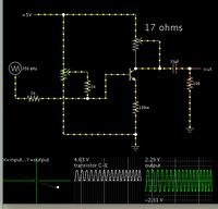
I'm checking with a simulation. I find I get an optimum result by using a collector resistor of 17 ohms. While I adjust that, I have been adjusting bias to keep the output centered vertically.

After doing this I find the transistor is conducting 300 mA at peaks. So it has a right to heat up (although this does not necessarily destroy it). I am operating it an an impedance of 17 ohms average.

The output impedance is not directly a part of the operation. I attach a 100 ohm load in series with a 33 uF blocking capacitor. However very little current goes through them, about 1/10 of what's going through the transistor.

Getting suitable voltage swing on the output is the important factor, as far as what we make our output impedance.

Notice that the output swing is great enough to hit flat spots at the peaks. This is distortion. A greater supply voltage would permit greater output swing.


Status
Not open for further replies.

Part and Inventory Search

Welcome to EDABoard.com

Sponsor

Back
Top