Continue to Site

Welcome to EDAboard.com

Welcome to our site! EDAboard.com is an international Electronics Discussion Forum focused on EDA software, circuits, schematics, books, theory, papers, asic, pld, 8051, DSP, Network, RF, Analog Design, PCB, Service Manuals... and a whole lot more! To participate you need to register. Registration is free. Click here to register now.

[SOLVED] Ignition Circuit Query

Status
Not open for further replies.

RMMK

Full Member level 3
Full Member level 3
Joined
Jun 12, 2013
Messages
163
Helped
1
Reputation
2
Reaction score
1
Trophy points
18
Location
Karachi
Activity points
1,461
I followed this circuit diagram for making my ignition Circuit and connected it to an ignition coil of a car but it does not produce any spark at the spark plug?? Where do I get it wrong??? Also I didnt had 3 in qty 22000 ohm resistors that is why i used 27000 ohm resistors in place of the two resistors connected at pin 2 of NE555 IC! the other 22000 ohm resistor is correct!


Also I am using a 12V 80 Amps Car battery for powering this circuit!


Plz help me on this!!!! NEED URGENT HELP :evil:
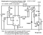
ignitor1(2).jpg

The Ignition Coil is not metal body bottle shaped one......... Its a standard Suzuki Cultus Coil!


When the Coil was connected with my circuit I didnt get ant potential difference w.r.t ground at pin 3...... but pin 4 and pin 8 shows 12 Volts! All I get is around 2 Volts at the base of transistor BC559 that is after 5.6Kohm resistor at pin 3! Even if I disconnect the whole Pin 3 with the 5.6K ohm resistor I am getting No output at Pin3..........

But when I disconnected this Ignition Coil from my circuit....... the Pin 3 showed a potential difference of around 11.86 V! Pin 8 and 4 showed 12.26 Volts!.......This 11.86V reading appears only when the 5.6K ohm resistor is disconnected from pin 3 of 555 IC!

Also with a disconnected Coil around 12 Volts appear at the terminals where coil is supposed to be located! With coil connected it disappears!

I am using a Digital Multimeter to check for voltages!
 

Hmmmm.....

The circuit is for a gas ignitor, as used in water heating boilers, with the right coil it produces about 10 sparks per second. It won't work with a car igniion coil, the ones it uses are much smaller and designed for lower power operation. From your description of the voltages you are seeing, I suspect you either have a wiring fault or TR1 is faulty. You will not be able to measure the voltage at pin 3 using a DVM because it is pulsed but if you connect an LED through a 1K resistor to it you should be able to see it flashing rapidly.

Brian.
 
  • Like
Reactions: RMMK

    RMMK

    Points: 2
    Helpful Answer Positive Rating
Hmmmm.....

The circuit is for a gas ignitor, as used in water heating boilers, with the right coil it produces about 10 sparks per second. It won't work with a car igniion coil, the ones it uses are much smaller and designed for lower power operation. From your description of the voltages you are seeing, I suspect you either have a wiring fault or TR1 is faulty. You will not be able to measure the voltage at pin 3 using a DVM because it is pulsed but if you connect an LED through a 1K resistor to it you should be able to see it flashing rapidly.

Brian.

So what do u propose? Should I change this Ignition Coil? What kind of a coil should I choose then? Okay I will test it out whether TR1 is okay or not.......... Sir I also followed your advice on that LED stuff and yes it blinked! plz help me on this one!
 
Last edited:

Why dont I just power up this Ignition coil with a 12 V Alternating Current without this ignition switch? Will it work?? plz help!
 
Last edited:

Now you are getting somewhere...

'You can run but you can't hide' :)
 

Now you are getting somewhere...

'You can run but you can't hide' :)

So you are saying that its possible? Plz confirm! because I dont wanna ruin my coil okay! it costs some real bucks u know!
 

Come back with results after doing it.
Those coils are abundant at any wreck yard for a about a dollar... :)
 

First you must tell us what you are trying to achieve. The circuit you gave is designed to drive a much smaller coil than you would find in a car but more importantly, it produces a continuous stream of sparks at 1/10th second intervals. It might work in an engine if it's doing exactly 600 RPM but not at any other speed!

If you are trying to improve the strength of spark at a spark plug to improve engine performance you should be looking at a different kind of circuit, one called 'CD ingnition' in which a high voltage is generated electronically, used to charge a capacitor then the charge is dumped into the ignition coil with a switching transistor.

Brian.

No No! I dont intend to do anything like that! I just want to ignite the air-fuel mixture in the combustor of my micro gas turbine which I am building for my project! So I want just a continuous streak of sparks nothing else!
Externet I will try replicate what u said today and post the results but the thing is I need this set-up to be handy too! A wall socket aint gonna be handy u know until unless I go for wireless energy transfer! :lol:
 
Last edited:

"Why dont I just power up this Ignition coil with a 12 V Alternating Current" Ignition coils don't work like conventional transformers. They have a much lower inductance because they need the primary current to rise to its maximum value in a period of a few milliseconds. When the contacts open, the stored energy then causes the coils to ring (thats why they have a capacitor across them), this ringing frequency is some where in the order of 50 -100KHZ. Of course they do not actually ring because as the secondary voltage rises it then sparks the plugs, but if no plugs are connected they would actually give a train of ringing pulses.
The first thing to do is to put the electronics on the side and short out the position of TR2 and make sure that every time you remove the short you get your required spark (use a screwdriver!!). Once you have proven that the coil wiring /rating/spark plug is OK. put back in the electronics and short IC1 Pin 3 to earth and prove that you still have your spark. I am still worried about the voltage rating of TR2 its only 110V.
Frank
 
  • Like
Reactions: RMMK

    RMMK

    Points: 2
    Helpful Answer Positive Rating
"Why dont I just power up this Ignition coil with a 12 V Alternating Current" Ignition coils don't work like conventional transformers. They have a much lower inductance because they need the primary current to rise to its maximum value in a period of a few milliseconds. When the contacts open, the stored energy then causes the coils to ring (thats why they have a capacitor across them), this ringing frequency is some where in the order of 50 -100KHZ. Of course they do not actually ring because as the secondary voltage rises it then sparks the plugs, but if no plugs are connected they would actually give a train of ringing pulses.
The first thing to do is to put the electronics on the side and short out the position of TR2 and make sure that every time you remove the short you get your required spark (use a screwdriver!!). Once you have proven that the coil wiring /rating/spark plug is OK. put back in the electronics and short IC1 Pin 3 to earth and prove that you still have your spark. I am still worried about the voltage rating of TR2 its only 110V.
Frank

Umm I used the screw driver to short out the TR2 and yes I got the sparks at the spark plug end! But when I short circuited the Pin 3 of IC1 it didnt do anything!! what should I do now???:?:
 
Last edited:

Hmmmm.....

The circuit is for a gas ignitor, as used in water heating boilers, with the right coil it produces about 10 sparks per second. It won't work with a car igniion coil, the ones it uses are much smaller and designed for lower power operation. From your description of the voltages you are seeing, I suspect you either have a wiring fault or TR1 is faulty. You will not be able to measure the voltage at pin 3 using a DVM because it is pulsed but if you connect an LED through a 1K resistor to it you should be able to see it flashing rapidly.

Brian.

Sir When I used the LED it was not blinking rapidly.......... rather it was blinking after quite a delay! Is it might be because of 27k ohm resistors I used in place of 22k ohm ones??? plz help!
 

The 555 is wired in astable configuration and with 22K resistors it will produce (in theory) 9.936Hz pulses with a 66.6% duty cycle. Each pulse should produce one spark.

With 27K resistors the frequency will change to about 8Hz so you should get 8 sparks per second instead of 10. Other than the frequency, nothing changes.

The most likely reason your output transistor isn't switching is that the output of the 555 is not reaching a high enough voltage to turn TR1 full on and off, a different make of IC might help. A crude but inefficient fix might be to change TR1 to an NPN device, remove the 22K resistor and diode completely, connect Tr1 emitter to ground, collector to the base of TR2 and the 100R straight to 12V.

Brian.
 
  • Like
Reactions: RMMK

    RMMK

    Points: 2
    Helpful Answer Positive Rating
The 555 is wired in astable configuration and with 22K resistors it will produce (in theory) 9.936Hz pulses with a 66.6% duty cycle. Each pulse should produce one spark.

With 27K resistors the frequency will change to about 8Hz so you should get 8 sparks per second instead of 10. Other than the frequency, nothing changes.

The most likely reason your output transistor isn't switching is that the output of the 555 is not reaching a high enough voltage to turn TR1 full on and off, a different make of IC might help. A crude but inefficient fix might be to change TR1 to an NPN device, remove the 22K resistor and diode completely, connect Tr1 emitter to ground, collector to the base of TR2 and the 100R straight to 12V.

Brian.

and the base of TR1 to 5.6K ohm resistor right? And will any NPN transistor will work for TR1?? Plz suggest a name if it is necessary! THANKS!!!


Brian.[/QUOTE]

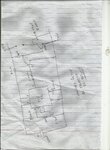
444444444444444444.jpg

Is this how u want it to be set-up??? also does BC546/ BC549 will work as NPN ones here???
 
Last edited:

The schematic is correct but treat it as experimental, if I were building this I would be looking at power MOSFETs rather than bipolar transistors.

When conducting (555 output high) you want the small transistor to be fully saturated so it's collector voltage is a low as possible, The BC546/549 only just meets this requirement but a bigger problem is they are only rated at 100mA absolute maximum collector current and in conduction the 100 Ohm load resistor will pass almost 120 mA. You could increase the resistor to 120 Ohms but that still leaves no safety margin and the higher it's value, the less likely it is that the 2N3055 will have enough base current to saturate.

There are lots of better suited transistors but before I make suggestions, please tell me where in the World you are and how easy it is for you to get components.

Brian.

I hail from Pakistan and am currently living in Karachi! I am a 2nd Year student of Mechanical Engineering and i think I might be able to fetch electronic components from the market relatively easier than other parts of my country! Lets see if the same goes this time around too! :roll:
 

That's good - where I am the nearest component supplier is over 100Km away so I have to order everything by mail.

What you are looking for is an NPN transistor that is rated with IC more than 150mA and a VCEsat of less than 0.6V at 150mA. The lower the VCEsat the better. Possible types are: BC548, 2N3904, ZTX853.

Brian.

Funny but I think my Astable configuration is faulty because when I connect my LED with Pin # 03........ it failed to blink even once! What do u think??? If what I think is correct what should be the way out??? I will visit the market tomorrow and will try to follow your instructed circuit diagram!!
 

Status
Not open for further replies.

Similar threads

Part and Inventory Search

Welcome to EDABoard.com

Sponsor

Back
Top