Continue to Site

Welcome to EDAboard.com

Welcome to our site! EDAboard.com is an international Electronics Discussion Forum focused on EDA software, circuits, schematics, books, theory, papers, asic, pld, 8051, DSP, Network, RF, Analog Design, PCB, Service Manuals... and a whole lot more! To participate you need to register. Registration is free. Click here to register now.

Identifying a faulty diode in a series of LEDs.

Status
Not open for further replies.

thinkanish

Junior Member level 2
Joined
Mar 11, 2012
Messages
20
Helped
0
Reputation
0
Reaction score
0
Trophy points
1,281
Activity points
1,429
Hi,
friends, I am stuck in an issue here...
Problem:
Need to Identify the faulty LED in a array of LEDs connected in serial fashion.

Solution tried:
A Resistance is also added in series along with the LEDs. Then all LEDs except one is bypassed (shorted) and the voltage on the resistance is measured. I thought this might provide better results. But on the contrary, while shorting and testing, when the last LED is tested, it blows out due to high current :(

Any one got some idea how to do this?

Thanks.
 

I'm confused, what exactly are you trying to identify? Are all the LEDs unlit because one in the chain is open circuit?

If one is faulty, the easiest solution is to bridge each one with another LED, if you bridge a good one, they will both light but slightly dimmer, if you bridge an open circuit one, it and all the others will light up as normal. Alternatively, if you have a voltmeter, connect it across each LED in turn, if one shows a much higher voltage than the others, it is the faulty one.

Brian.
 

Hi Brian,
Thanks for your reply.
But I am working on the circuit exactly similar to this: **broken link removed**

And they are using a ic called AAI406 for fault detection and correction. How can I implement the same without that IC and with a MCU? I can use a MCU (TI MSP/PIC/atmega)

Thanks.
 

If you apply power, then measure across each led with a voltmeter, the bad one will yield a reading.

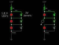
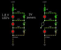
I wonder if this method will suit your purpose for an led string being installed? A zener diode in parallel with each led.


Where fail safe is needed, I use the same Zener diode trick, it also has the advantage of protecting the LEDs against reverse polarity voltages, In my case (underwater lighting) I use "Jade" series LEDs which have a Vf of about 3.1V so I use 3.6V Zeners. If you use this method, make sure your Zener diodes are rated to withstand the LED current.

I'm uneasy about the AAL406 because it's 'on' (latched) SCR voltage may be lower than that of the LED and consequently force more current through the remaining ones. Certainly it would work with some LEDs but I'm cautious about ones with high Vf. If you really have to monitor for faults, I would take the simpler approach of monitoring the current through the chain and checking it is within limits. Provided you are not using a constant current source, you can do this quite easily by measuring the voltage drop across a series resitor in the 'ground' side of the LEDs with an ADC. Alternatively, if you are using constant current, measure the voltage across the chian instead.

Brian.
 

Thankyou guyz, that design looks promising. I ll try that and post. By the way, can i monitor that using a MCU and tell which LED was blown out? Like in your example, the second one was out. Can i interface it with a mcu to report that?

Thanks.
 

It's difficult to identify which LED is out although the methods described earlier can tell if one or more somewhere in the chain are faulty.

To monitor each LED there is a problem because the voltage at each junction would have to be measured. It's more difficult than it sounds because the voltages step up by one LED Vf at each stage and will quickly exceed the limit for a 'naked' ADC input. You could add circuitry that measures across each LED but that would be difficult because the lower voltage point would still probably be higher than an ADC could handle. A more practical solution would be to use a potential divider from each junction to divide the supply voltage down to the maximum for the ADC. Bear in in mind that if the botom LED went open circuit, all the remaining ones would go up to supply potential.

How many LEDs are you expecting to have in a chain and what supply voltage are you using?

Brian.
 

Hi, the array contains 6 LEDs and supply is 5 volts.
by the way, if the condition for bottom LED failure is taken into account, and a divider is designed, then the voltages can be sampled and compared. Can i implement it by this way? I mean this will be the extreme condition right?
 

Hi, the array contains 6 LEDs and supply is 5 volts.
by the way, if the condition for bottom LED failure is taken into account, and a divider is designed, then the voltages can be sampled and compared. Can i implement it by this way? I mean this will be the extreme condition right?

Yes it would have been helpful if I'd made the simulator show volt levels between the led's. With the zener method an open led results in the value of the zener appearing across it.


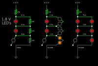
Here's a screenshot of a few more methods:

(1) a resistor in parallel with each led.

(2) a 2-led string in parallel with each led (or as an alternate, an led which has a greater fwd V).

(3) parallel identical led's.


#3 is not very satisfactory. Two parallel led's need to have matching fwd V's, or they will not be the same brightness. One led going open will produce no change in volt differential. Moreover it will put the entire burden on the other led, which may cause it to go bad too.
 
Hold on - if your array has 6 LEDs and runs on a 5V supply, they can only be wired in series in one way, that is, 3 parallel strings, each with two LEDs in series. Any othe rcombination isn't a series circuit or runs out of volts.

With two LEDs in series, you can measure the voltage at their center point with a standard MCU ADC as it will never exceed their 5V limit (assuming you are using a 5V MCU!). With a series resitor in the +Ve end of the chan, the junction of the LEDs should be Vf. If it's higher the bottom LED is open circuit, if it's lower, either the bottom LED is shorted or the top one is open circuit.

You do need one ADC input to check each pair of diodes though.

Brian.
 

Dude, I am actually working on a street lamp which contains 2 channles of 6 LEDs in series. This damn thing powers up and delivers a optimal light at 5 volts itself. If you dont mind, here is the link to the datasheed of the LED
**broken link removed**

I am sorry if I caused any inconvenience.
By the way, which software you used for that simulation thing?
 

There is more to this light than just the LEDs. If each LED has a Vf of 3.3V only one can be run directly from 5V, even with two in series it would need 6.6V. I think there must be an inverter somewhere in the circuitry to boost the voltage from 5V up to 6 x 3.3 = 19.8V. Fault detecting just got a whole lot more complicated because you need to know how stable that voltage is and whether it's continuous or pulsed. Can you provide a complete schematic?

Brian.
 

the best white LED's will include back to back zeners for ESR protection, since Vr=-5Vmax, this can also serve as forward drop protection in case of open circuit. The best modules will use constant current regulation with enough headroom to allow for Vf variation of 10% or more.

THe information supplied so far is inconsistent. Please re-phrase your question.
 

Hi,
Yes, the lamp contains some circuitry. I will analyze the circuitry and post it soon. Also, i will post a snap of the circuit if I cant analyse it. But I am sure about the voltage. it powers at 5 volts (all 12 LEDs) and they consume 300mA current (I checked this with the rps)

And brian, what simulator u used to for the circuits you posted here?

Regards.
 

Dude, I am actually working on a street lamp which contains 2 channles of 6 LEDs in series. This damn thing powers up and delivers a optimal light at 5 volts itself. If you dont mind, here is the link to the datasheed of the LED
**broken link removed**

I am sorry if I caused any inconvenience.
By the way, which software you used for that simulation thing?

1.

I believe you're asking about my schematics above. I'm using Falstad's interactive animated simulator at:

www.falstad.com/circuit

This link will open the website, load my schematic, and run it on your computer. (Click Allow to load the Java applet.)

https://tinyurl.com/d9dkteb

You can change things around at will. Right-click on a component to bring up an edit window.

2.

For decades the conventional advice has said don't put led's in parallel...
that is, unless a balancing resistor is installed at each led (as shown in the article you linked to, page 14 circuit B).

However in recent years it appears that manufacturers have become able to achieve closer matching of current versus voltage, at least in the same batch of led's. A few have found a way to gang led's in parallel, by applying some esoteric knowledge which still looks like magic to the rest of us. (The simplified version is shown on Page 14 circuit A, using one safety resistor.)

I think it was SunnySkyGuy who explained the way to successfully run bright led's in parallel.
 

Hi guys,
You are right. The lamp contains a boost circuit which converts the 5 volts to 22volts for supplying the 6 LEDs. There are two channels from the circuit board each channel outputs 22volts and each channel supplies power for 6 LEDs in series. I can tap the connections from the LED terminals. Also, I came out with a schematic to interface it with the microcontroller. But i am not sure whether it will work. Will post the schematic soon.

EDIT:
Here is the schematic I thought of:
circuit.png

Now my question is this: Is the above configuration reliable/feasible?
And my idea is to give the base each transistor to a MCU pin. And the program is to consecutively writing "1" on each pin in cyclic order thus turning on the tansistor which provides a short. Now, the short which again lights up the circuit can be taken as the place of defective LED. Can this be implemented?

Regards,
Anish
 
Last edited:

Here is the schematic I thought of:
View attachment 82504

Now my question is this: Is the above configuration reliable/feasible?
And my idea is to give the base each transistor to a MCU pin. And the program is to consecutively writing "1" on each pin in cyclic order thus turning on the tansistor which provides a short. Now, the short which again lights up the circuit can be taken as the place of defective LED. Can this be implemented?

Regards,
Anish

The idea is clever.

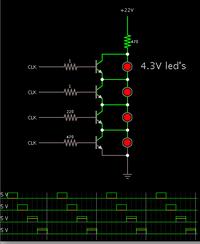
I tried a simulation.


I assumed the mcu outputs a 5V signal.

As you intended, the 5V signal is high enough to turn the bottom 1 or 2 transistors on and off. The scope traces show that current flows from the bottom 2 clock signals, turning on the transistors.

However at higher levels, the 5V signal must overcome a higher threshold voltage. It is not sufficient. Notice the scope traces. Yellow indicates current. The top 2 clock signals go to 5V, but their current stays at zero. They cannot turn on their transistors.

Here is a link duplicating my layout in the simulator. You can watch it in action on your own computer. You can disconnect the led's to see what results.

https://tinyurl.com/bpgprar
 

The bottom transistor will turn on when about 0.6V is exceeded but as you go up the 'chain' each needs 0.6V + (number of LEDs * Vf) so to get the top transistor to turn on you have to provide (3 * 3.3) + 0.6V = 10.5V or more. This can't be produced by logic output of a microcontroller without additional interface circuitry.

One option would be to use an opto-coupler with current amplifier instead of the single transistor. The LED side of the opto would need the same voltage to turn it on regardless of where in the chain it sits.

There is one major flaw in your reasoning though, you assume the faulty LED has gone open circuit, it is possible it has short circuit or even in rare cases, become a resistor and not emitting any light.

Brian.
 

There is one major flaw in your reasoning though, you assume the faulty LED has gone open circuit, it is possible it has short circuit or even in rare cases, become a resistor and not emitting any light.
Yeah I can understand that dude. But for now, I am doing for the open circuit case alone.
One option would be to use an opto-coupler with current amplifier instead of the single transistor. The LED side of the opto would need the same voltage to turn it on regardless of where in the chain it sits.
Yeah this approach also suggested by some friend I think. What do you mean by a "opto-coupler with current amplifier" ? Can you elaborate the circuit?

Thanks.

EDIT:
Does this config will work?

www.bit.ly/UkntLV

thanks.
 
Last edited:

The vast majority of opto-couplers can only handle a few mA through their output sides and nowhere near 300mA. If an LED was open circuit and you bridged it with an opto-coupler to maintain current flow, all the current would have to pass through it. A transistor biased through the opto could carry the current though.

I have had a thought (warning - this usually means trouble 8-O), there may be a different way of doing this. If each LED (working) drops 3.3V and the LED in an opto-coupler typically needs around 1.6V to turn it on, you could connect the input (LED) side of the opto across each white LED with a 2.7V Zener diode and say 100 Ohm resistor in series with it. Under normal operation, the white LED would maintain 3.3V across it and the opto wouldn't turn on. If the white LED went open circuit, the voltage across it would significantly increase, allowing the Zener and opto-coupler to pass current. You could then either interrogate each opto-coupler output to see exactly which LED was open circuit or you could wire-OR the outputs to give a single fault output.

Brian.
 

Status
Not open for further replies.

Part and Inventory Search

Welcome to EDABoard.com

Sponsor

Back
Top