Continue to Site

Welcome to EDAboard.com

Welcome to our site! EDAboard.com is an international Electronics Discussion Forum focused on EDA software, circuits, schematics, books, theory, papers, asic, pld, 8051, DSP, Network, RF, Analog Design, PCB, Service Manuals... and a whole lot more! To participate you need to register. Registration is free. Click here to register now.

I want to make SMPS power supply.

zxpa

Member level 1
Member level 1
Joined
Mar 27, 2024
Messages
34
Helped
0
Reputation
0
Reaction score
0
Trophy points
6
Activity points
204
I want to make SMPS power supply?

As a beginner I don't know are these circuits are workable?
Please if somebody who has more experience to recommend me the scheme I uploaded here?

All of these schemes are different power.

Is this scheme workable?
4-SG3525-12V_220V-Power-Inverter.png


Is this scheme workable?
vlcsnap-2024-06-05-22h44m51s613.png


Is this scheme workable?
1.png


Is this scheme workable?
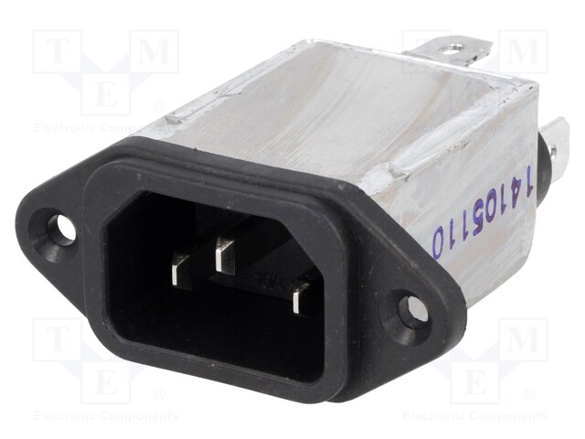
Does this EMI filter hase built in NTC resistor?
https://www.tme.eu/en/details/fyb10t1/iec-60320-connectors/yunpen-electronic/

1.jpg


Is this scheme workable?
There is transformer connected at 220V AC
Do I need 150W iron cored transformer for this circuit?
220V-12V-150W-switching-power-supply-circuit-diagram.png
 
Forget the last one, it isn't a power supply, its a lamp dimmer.
1. is a push-pull driver, it will work but isn't particularly efficient.
2, 3 & 4 are the same schematic, slightly different values but the transformer sets the output voltage. Without feedback they will not produce stable voltages under different load conditions.

All of these produce significantly different output voltages, if I was you, I would start by deciding what voltage you need, what current it has to supply and whether it should be stabilized (recommended). From there you can work out the best topology then find suitable components.

Brian.
 
Hi,

I want to make SMPS power supply?
Then do it step by step.
The very first step does not need any SMPS knowledge at all.
It´s simply your very own decision:
Specify the power supply:
* what´s your input voltage range
* is the input DC, or AC - which frequency
* what´s the output voltage (range) and tolerance
* what´s the nominal maximum current you will draw long term (over minutes, hours...)
* what´s the expectable maximum short term current over 100ms

It makes no sense to go the next step as long as you can´t write down these numbers. Nobody of us can give you these numbers.

Klaus
 
* what´s your input voltage range
AC 220V/50Hz
I will use this filter
0058812_FYB10T1.jpg


I don't know whitch NTC resistor value to use?
I don't know whitch Fuse value to use?

* is the input DC, or AC - which frequency
The input is AC 220V/50Hz (If You think about wall outlet).

* what´s the output voltage (range) and tolerance
0 to 35 Volts. I do not know how to define tolerance?

* what´s the nominal maximum current you will draw long term (over minutes, hours...)
35V/10A (350 Watts)

* what´s the expectable maximum short term current over 100ms
I think if you mean about "short circuit current"
https://www.linkedin.com/advice/3/what-formula-calculating-short-circuit-current-e1xdc
As a beginner I do not know how to determine it for my needs.
 
Hi,
0 to 35 Volts. I do not know how to define tolerance?
So you want it to be adjustable? How?

Tolerance: How exact you want it to be. Initially, vs temperature, vs time, vs load ...
You could use internet search for the definition.
Or you may just look at the datasheets of ready to buy power supplies .. how they define it.

I think if you mean about "short circuit current"
NO. Short time. Not short circuit.

As a beginner I do not know how to determine it for my needs.
We on the other side don´t know how you want to use your power supply .. or what you want to conect to your power supply.
Thus it´s rather difficult for us to give you good advice.

Think about it:
* One usually does not buy a power supply just to put it into a box. One usually wants to use it.
* you don´t go to a hardware store and asks for a screw ... without knowing what to use the screw for.

****
My recommendation:
It seems you are not very experienced with electronics .. and how do design electronics. If so ... building an 350W SMPS is not a good idea to start with.
Designing such an SMPS is not just connecting a couple of electronic devices. It Needs skills in math, understanding in electronics, HF design, high current design, PCB layout design .... Also handling mains voltage is dangerous. I´m not convinced that you know about safety rules.

Learn electronics step by step ... and do an SMPS design in maybe 2 years.


Klaus
 
For starter.
I will buy EMI Filter, NTC resistor and Fuse.
I will start building SMPS as 12V,1A for begin.
3-12v-1-amp-smps-circuit-1.png


7-12V-1-amp-smps.png


I found the circuit diagrams for PC power supplies
They all gives +12 Volts the output

I am going to do excercises of creating it.
I will excercise with output voltage change by transformer rewinding.

I will use protection material like:
Ear anti phones.
Eye protection glases.
Hand gloves.
Fuse switch.
Plastic transparent box - to protect myself from explosion (capacitor, transistor...)
Plastic tweezers.
Small metal screw driver with plastic handle - for trimer resistor setting

Plese if you or somebody tell me are these schemes are workable?
https://danyk.cz/s_atx_en.html
https://www.smpspowersupply.com/atx-power-supply.html
 
Here in red rectangle the DC polarized capacitors are connected into DC and AC main line together and 150K resistors are connected into DC and AC main line together?
Is it possible or is this circuit diagram is iregular?
I understand that it is not possible to connect AC and DC sources directly.
1-s_atx01a.png
 
To address your question: The arrangement of 4 diodes is visible inside the red area. It's a full diode bridge which converts AC to DC. Regardless of AC cycle direction, every current flow is steered toward the correct polarity to make a DC supply.
 
I don't understand what's your exact question. What do you mean with "DC main line"? It's a classical circuit for 115/230 V switchable SMPS input, switched between full bridge and doubler rectifier, used in most PC power supplies before PFC became mandatory.
 
I am sorry I didn't expressed myself right as "DC main line" I think only as DC.
--- Updated ---

I see that the input of the first capacitor "+" is connected into DC but the output of the same first capacitor is connected in series with the input of secound capacitor. In that middle there is line goes from filter into power switch. After power switch there is middle point of two the capacitors connected in series. This line takes from power switch is AC and it is directly connected with middle between two the capacitors but they are connected into DC.
 
Last edited:
With open switch, the circuit is working as bridge rectifier. 230 VAC in / 325 VDC out. With closed switch, it's turning into a voltage doubler. 115 VAC in / 325 VDC out.
See this explanation https://en.wikipedia.org/wiki/Rectifier#Voltage-multiplying_rectifiers
In voltage doubler mode, only the two upper diodes are in effect. The lower diodes a reverse biased and don't carry current.
 
Thank you for reply I understand it now.

This means that I need to use this circuit always with open switch for the reason that my wall power outlet is AC 220V/50Hz. I must not never close the switch because I will make hazard.
 
This means that I need to use this circuit always with open switch for the reason that my wall power outlet is AC 220V/50Hz. I must not never close the switch because I will make hazard.
The straight forward solution would be to omit the switch at all.

Klaus
 
Yes thank you for advice.
And I think so.

The big two capacitors are expensive.
I already have capacitors 1000uF/400V

There in the scheme it is defined:
680 uF/250V

But I have found:
680uf/400V

at the market.

Can I use 680uf/400V instead 680uf/250V?
 
Last edited:
Hi,
Can I use 680uf/400V instead 680uf/250V?
You can´t calculate the expected capacitor voltage on your own ... but want to design an SMPS. Interesting.

In my days we were told to learn the basics first. Seems I´m outdated.

Klaus
 
It is very challenging to make a high power switch mode power supply if you have not worked on smaller similar things before - I strongly suggest finding some one in your area who has the required know how, and learning from them - apart from the magnetics and control and layout complexities - there is a safety issue.
 
350W SMPS power supply "kickback" voltage - how to remove?

How to remove "kickback" voltage?

I started to making an SMPS by this circuit diagram:
1-3-smps2B3002Bwatt2Baudio2Bamp2Bpower2Bsupply2Bcircuit.png


I finished the circuit until this point:
2.png


When I connected both of transistors my multimeter shows me that voltage is too
hight and indicates that it cannot measure it. The maximum value for my multimeter is 1000 V.

3.png


By Google search I found that this effect is called kicback voltage.

IR2153 circuit works at frequency of 50 kHz.

The Formula for IR2153 circuit is:
F=1/(1.4 x (R+75) x C)
F=1/(1.4 x (47000+75) x 0.0000000003F)
F=1/(0.00000000042 x (47000+75))
F=1/(0.00000000042 x (0.00000000042 x 47000 + 0.00000000042 x 75))
F=1/(0.00000000042 x (0.00001974 + 0.0000000315))
F=1/(0.0000197715)
F=50577.8519586273170978
F=50.577 kHz

Is this behaviour normal for a SMPS power supply?

Everything works normaly and no component is overheat.

Just one component is heat. The word is about 22K/5W resistor. I think it is normal for
it be relative hotter.

Can SMPS power supply work continously under kickback voltage?

I connected two UF4007 diodes from negative to positive rail but kickback voltage is still present.

4.png


The UF4007 diodes did not burned up and they are regular.

I turned off the circuit and tested them with multimeter.

All the circuit is connected with 220V/75W incandescent light bulb in series.

By this way I make sure that if I connect something in iregular way I secured not to make a hazard like components overburning or explosion of two large
bulk capacitors.

When I connect the circuit into wall outlet (220V AC/50Hz) the bulb lights up just for a short moment, for a piece of secound and silent high pitch sound is heared from bulk capacitors.

After that the bulk capacitors are charged up very fastly and the bulb not shines anymore.

By this way I secured that all of the components in the circuit are connected in regular way.

I have an old SMPS PC power supply.

Model:
NEO
PM-230RDEGN QC OK

When I measured the voltage at input of primary coil of main ferrite transformer my multimeter shows me the same result like it cannot measure the voltage because it is too high over 1000V.

I realised that this model of PC PSU works normaly with kickback voltage.

As a beginner in creating of SMPS power supply I am not sure?

I asked a person who is an electronics proficient with experience and the same person tould me that kickback voltage does not disturb the power supply.


Attachments

  • 2.png
    2.png
    1 MB · Views: 47
Last edited:
Hi,

where exactly did you connect your multimeter ( 2 wires)?

And if you connect the primary of the transformer .... be sure to also connect the secondary of the transformer.
Don´t use the primary only!

Klaus
 

LaTeX Commands Quick-Menu:

Similar threads

Part and Inventory Search

Welcome to EDABoard.com

Sponsor

Back
Top