Winsu
Full Member level 3

Hi All,
I need to modify an existing circuit that uses the PIC32MX695F512H. I just need to use two digital I/O. I have identified the pins that I want to use:
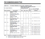
Pin 54 will be a digital input which will be connected to another IC. That IC will pull down the signal to cero ( 0.3v) when an event happens. So I'm planning to use a pull-up resistor connected to Vdd( 3.3V). Using a 10k resistor I should be in safe side, but I would like to do the calculations ( knowing what I'm doing) and fully understand it as I'm not very familiar with microcontrollers. I can read some relevant information about currents In and Out from I/O pins and I don't know which one applies to my case. On page 360 I can see Icnpu ( change notification Pull-up current) which is 50uA.On page 361 I can see Input high injection current which is 5mA. on page 362 I can see Iol<10mA, Vdd = 3.3v( for all I/O pins not defined as 8x sink diver pins) and Iol<15mA. What current this pin would tolerate? and would it recognize 0.3V as Low and 3.3V as high?.
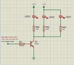
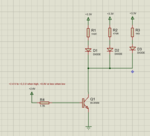
Pin 42 will be a digital output. It will be used to disable some LEDs which are permanently on, it will be done by connecting the digital output to the base of a transistor, then I can control the LEDS that are permanently on.
The relevant information that I have found is the next: On page 362 Output low voltage is 0.4V and output high voltage is 2.4V and Iol and Ioh cange from 10mA to 15mA. I wonder if this is the output range voltage that I can expect to choose the transistor and if that is current range that I can expect as well to attack the base of my transistor. I'm a bit confused also about the diference between source driver pins and not defined as source driver pins.
Any help would be very appreciatted.
Regards,
Winsu


