Continue to Site

Welcome to EDAboard.com

Welcome to our site! EDAboard.com is an international Electronics Discussion Forum focused on EDA software, circuits, schematics, books, theory, papers, asic, pld, 8051, DSP, Network, RF, Analog Design, PCB, Service Manuals... and a whole lot more! To participate you need to register. Registration is free. Click here to register now.

[SOLVED] I need help understanding measurements / dimention markings on a datasheet

Status
Not open for further replies.

Xenobius

Member level 5
Member level 5
Joined
Feb 25, 2019
Messages
84
Helped
0
Reputation
0
Reaction score
0
Trophy points
6
Activity points
850
Hi all,

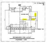
So I am trying to draw a package for a micro SD card holder from Molex however I cannot quite understand some of the markings.
For example some markings are simple 1.8 meaning 1.8mm however others are for example 2-5.14... or 2-1.0... what does it mean?
Capture.PNG

https://static6.arrow.com/aropdfconversion/af53f7712567bd056763f4323b2743c483def1df/1040310831_sd.pdf

Thank you
 

Consider that the N-xx.x syntax refers to dimensions occurring multiple times. In case of 2-5.14 this is a bit confusing because 5.14 is also printed separately for the upper pin.


You could also consider that the picture is the copy of a correctly dimensioned CAD drawing. So you can always scale it accordingly and check the dimensions with a ruler, or even convert it to dxf and use it to check your footprint pin placement.
 

i don't think that drawing is correctly dimensioned

the current practice is to measure everything from one reference, usually the lower left
so that tolerances do not build up

the values in the drawing are likely correct, as Molex is reliable, but the drawing does not follow best practices

as for the drawing being a copy, it looks like a small piece of the drawing in the link
there is no reason to believe photocopies and PDFs maintain dimension
if you measure the drawing, start by checking several short dimensions and several long dimension in both directions
 

the current practice is to measure everything from one reference, usually the lower left
Should be so, but incremental dimensions seem to be popular, particularly in Japanese and Chinese data sheets. No reason to assume that the dimensions are wrong.

- - - Updated - - -

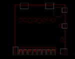
You can download a STEP 3D-file from Molex and export it to *.dxf
Should give you exact dimensions.

1040310811_sd.PNG
 

Attachments

  • 1040310811_sd.zip
    4.2 KB · Views: 241
Ureka moment! 8-1.1 means qty 8, size 1.1mm
 

Better still read the DXF into your cad package and use as a base for the component.
 

Status
Not open for further replies.

Part and Inventory Search

Welcome to EDABoard.com

Sponsor

Back
Top