Continue to Site

Welcome to EDAboard.com

Welcome to our site! EDAboard.com is an international Electronics Discussion Forum focused on EDA software, circuits, schematics, books, theory, papers, asic, pld, 8051, DSP, Network, RF, Analog Design, PCB, Service Manuals... and a whole lot more! To participate you need to register. Registration is free. Click here to register now.

I need assistance tracking down failed component on old RCA amplifier

pityocamptes

Junior Member level 2
Joined
Sep 12, 2012
Messages
21
Helped
0
Reputation
0
Reaction score
0
Trophy points
1,281
Visit site
Activity points
1,461
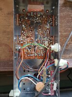
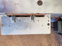
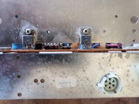
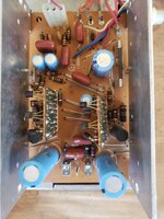
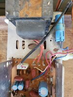
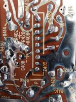
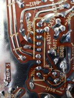
The right channel is being amplified, the left is not. I tested the transformer voltage on both outputs and trans is working at around 23v per leg. At the output im getting around 4 volts or right, 0 on left. You can still hear unamplified signal through left channel though. Does anyone based on the pic have an idea where I can start taking readings? I have VM. Any help appreciated. Thx
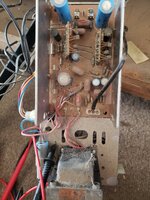
 

Attachments

  • 20241228_150141.jpg
    20241228_150141.jpg
    1.8 MB · Views: 37
Do you have a schematic ?

If not hand draw one.

Old carbon comp resistors often fail out of spec. Old electrolytic caps also
subject to failure, their electrolyte drying out.


Regards, Dana.
 
Here are some numbers...
--- Updated ---

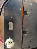
I would start by using a soft dry paintbrush to remove all the dust then show us a new photograph and include a shot from the underneath of the board.

Brian.
Ok. I can do that.
 

Attachments

  • 20241228_163219.jpg
    20241228_163219.jpg
    1.2 MB · Views: 21
Usual way:
- signal tracing along amplifier channels
- checking bias points of amplifier stages
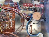
There are apparently electrolytic capacitors in the signal path, e.g. C416 and it's counterpart, probably more around the vertical amplifier boards. They are first candidate for aging fault. It's often possible to measure capacitance in circuit.

Signal tracing should clarify if the fault is on the main board or the vertical modules.
--- Updated ---

For simple circuits like this, I prefer to sketch a schematic as first repair step.
 
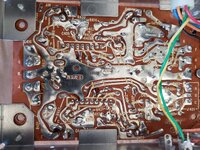
K appears to be the common output ground for audio and is working. Channel J is working, Channel L is not. I have cleaned up the board any ideas where to start measuring on Channel L and comparing to Channel J is appreciated.
--- Updated ---

So on each terminal for both sides of external boards connected to pcb i had same readings for both sides at each terminal.
--- Updated ---

So I've been comparing voltage at each terminal with ground probe on ground and found that voltages are the same for each channel L and J up to the point you get to the big caps at terminal output. Measuring the working channel I get around 4 to 5 volts. The non working channel is 0. Can I assume the cap is bad? Thx
 

Attachments

  • 20241229_113302.jpg
    20241229_113302.jpg
    2.1 MB · Views: 17
  • 20241229_113253.jpg
    20241229_113253.jpg
    1.8 MB · Views: 20
  • 20241229_113244.jpg
    20241229_113244.jpg
    1.4 MB · Views: 23
  • 20241229_113232.jpg
    20241229_113232.jpg
    1.6 MB · Views: 25
  • 20241229_113222.jpg
    20241229_113222.jpg
    1.3 MB · Views: 21
  • 20241229_113212.jpg
    20241229_113212.jpg
    1.4 MB · Views: 22
  • 17354980626148700471473134812188.jpg
    17354980626148700471473134812188.jpg
    1.5 MB · Views: 18
  • 17354980885938946566415775833573.jpg
    17354980885938946566415775833573.jpg
    1.5 MB · Views: 20
Last edited:
Can you tell if C is a coupling cap ?

That C connection sure looks unsoldered (Lower left connection coming thru board) :

1735504758891.png


You could pull the cap, measure it. If you dont have a C meter use it in a RC Network and measure its
time to charge when a step V is applied to it, and calc its value. Or just try a close valued C and see if
that roughly works.....

 
Last edited:
I'm confused. Not the best at circuit theory been a long time and my oscope is buried in a box, doing home renovations at moment. I removed both caps. On circuit J the 1000uf cap on + pad it shows 32v temporary cap placement, doesn't matter which cap i pulled, shows neg output at around 5 volts. However circuit L shows 32v at + pad for cap, the minute you attach a cap the output leg of cap drops to zero... why?
 
Without a schematic to tell us what connects together it is impossible to tell. Capacitors don't conduct DC when charged so if connecting one causes a change in voltage there is a good chance it is short circuited internally. Removing capacitors can cause other effects such as instability or lack of filtering which can make DC measurements change so it isn't conclusive but it would be unusual for an otherwise high voltage to go to zero when a capacitor is connected. Given the age of the amplifier and poor quality of the components generally, it would be a good idea to change all the electrolytic capacitors for new ones, they deteriorate gradually and I would guess that amplifier dates back from around 1970 so it is 50+ years old already.

Brian.
 
Yes its an old unit. To clarify I pulled both caps off the board. Circuit J was working fine, circuit L was not getting amplification. So I swapped the caps, the known working side cap to the other. Still doesn't work, but I find it interesting that on the side that does not work cap pad + is 32v once the known good cap is placed on the pad, the neg side of cap leg is zero, whereas when trying this on the good circuit its around 5v. Let me see if I can find a schematic maybe that could help. Thx
--- Updated ---

Looks like its a VTT310L trying to see if I can find schematic
 
Last edited:
Can your measure any voltage live across a suspect joint or across a capacitor for wild fluctuation. normally Caps should have a steady DC voltage across them unless it is a shunt filter at ground level.
I have used caps in circuits that NEVER have a constant DC: coupling caps, or as part of an oscillator or a timing circuits or a voltage doubler or...

Again, without a schematic all people can do is make wild guesses.
 
amp6.jpg


RCA pubished lots of "reference designs" and I would guess this is one of them. I have attached a typical design that seems to be similar. Unfortunately it doesn't provide component references to cross reference with the PCB. It might help, I can't find a schematic exactly matching that model. Note that the small black transistors were usually made by Motorola but they do not have modern part numbers printed on them.

In cases of restoring older equipment like this I'm afraid it is usually down to hand tracing a schematic and using intuition and some guesswork to identify some of the components.

Brian.
 
It's simpler circuit, apparently 2 power and 4 driver transistors per channel. Power transistors seem to have same (npn) polarity.

First step could be to check bias voltage of power transistors with voltmeter.
 
Thx. So I checked all voltage references for both L (channel works) and R (channel does not work) sides. They were either spot on with each other or within 5% max. As mentioned when I measured C416 cap (+) pad I have the same voltage as C417 cap (+) pad. After that its zero. So is there a problem with C416 cap (-) -> 154 -> 155 -> ground? If so how do I test? Thx
 

LaTeX Commands Quick-Menu:

Part and Inventory Search

Welcome to EDABoard.com

Sponsor

Back
Top