T
treez
Guest

Hello,
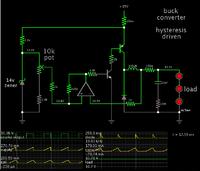
The below is the schematic of my attempt at doing a simulation of a hysteretic buck converter.(LED driver)
The idea is that one comparator will turn off the FET when the inductor current reaches the peak, and the other comparator will turn the FET ON when the inductor current reaches the trough.
However, unfortunately, it doesn't work, as a little "glue" logic is needed, and I haven't quite got this right yet.
Do you know how I can make this work?
schematic and LTspice simulation attached


