Continue to Site

Welcome to EDAboard.com

Welcome to our site! EDAboard.com is an international Electronics Discussion Forum focused on EDA software, circuits, schematics, books, theory, papers, asic, pld, 8051, DSP, Network, RF, Analog Design, PCB, Service Manuals... and a whole lot more! To participate you need to register. Registration is free. Click here to register now.

HV9821 LED driver current sense resistor conenction is wrong?

Status
Not open for further replies.
T

treez

Guest
Newbie level 1
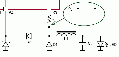
On page 3 of the HV9821 LED driver datasheet, howcome on page 3, the high side current sense resistor is connected to ground?

HV9821
**broken link removed**

So there could be 700V one side of this resistor, and then ground on the other side of this resistor?
 

the high side current sense resistor is connected to ground?
I don't see a ground connection of Rs.
 
  • Like
Reactions: treez

    T

    Points: 2
    Helpful Answer Positive Rating
on the "functional block diagram...inside the controller there is a ground symbol.
 

But the IC hasn't a ground pin. The block diagram clarifies that the ground symbol refers to the OUT pin.
 
  • Like
Reactions: treez

    T

    Points: 2
    Helpful Answer Positive Rating
But the IC hasn't a ground pin. The block diagram clarifies that the ground symbol refers to the OUT pin.

I agree, but why is the Rs connected to it?
 

Output current is sensed at the OUT pin, I think. So what's strange about it?
 
  • Like
Reactions: treez

    T

    Points: 2
    Helpful Answer Positive Rating
The buck freewheel diode cathode is grounded in their diagram
May be I didn't yet get your point, but the diode connection is also typical for a buck converter.
 
  • Like
Reactions: treez

    T

    Points: 2
    Helpful Answer Positive Rating
I really don't get your point. :?:

Very regularly, the cathode is grounded. The anode is not grounded.

8307946600_1366531991.gif
 
  • Like
Reactions: treez

    T

    Points: 2
    Helpful Answer Positive Rating
but your picture shows the anode of D1 directly connected to ground , as it should be.

If you open out that picture above, you would see the cathode of D1 has got a ground connection , which it shouldnt have.
 

You are confusing the substrate connection inside the chip with a ground connection. See my post #4.
 
  • Like
Reactions: treez

    T

    Points: 2
    Helpful Answer Positive Rating
Status
Not open for further replies.

Similar threads

Part and Inventory Search

Welcome to EDABoard.com

Sponsor

Back
Top