cg_shura
Newbie level 1

Faced with such a problem. CSS (clock security system) is enabled for the STM32F205RET6, when an HSE fails, an NMI interrupt is generated. I register the failure fact in BKPSRAM STM32 and do a reset. The board works with Ethernet and GSM. Only when working with GSM (SIM800C) sometimes I fix a non-zero CSS hit counter.
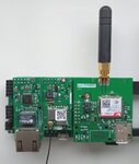
The GSM antenna is like that. With an antenna on the cable 2 m is better, but it should work with the antenna nearby.
It was not possible to achieve CSS on the table, which I just didn’t do. I tried to work without an antenna - SIM800C works without an antenna, all the base stations are nearby. I connected an equivalent in the form of 4 resistors 1206 of 200 Ohms instead of an antenna, also works without problems as well as without an antenna. I tested the power supply (ST1S14) with an equivalent load of 2A - no problem.
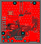
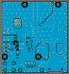
On the board - GSM in the form of a module. GSM power and ground are duplicated by the 4th legs of the PLS connector. Quartz STM32 make in accordance with all rules - it connects to the ground STM32 separately from the backward earth, there is a shielding loop around the quartz chains.


