elec-eng
Full Member level 5

Hi all,
I am currently implementing the PHY layer of a communication system. The transmitter has a pulse shaping filter followed by a DAC, as depicted below:

My question is:
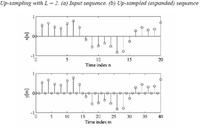
How up-sampling is being implemented in hardware on input data bits, i.e. is it implemented by zero padding or by just repeating bits
for example, the pattern 1 0 1 , how will it look like after up-sampling if the OSR=8
would it be 10000000 00000000 10000000
or 11111111 00000000 11111111

Thanks
I am currently implementing the PHY layer of a communication system. The transmitter has a pulse shaping filter followed by a DAC, as depicted below:

My question is:
How up-sampling is being implemented in hardware on input data bits, i.e. is it implemented by zero padding or by just repeating bits
for example, the pattern 1 0 1 , how will it look like after up-sampling if the OSR=8
would it be 10000000 00000000 10000000
or 11111111 00000000 11111111

Thanks


