boylesg
Advanced Member level 4

- Joined
- Jul 15, 2012
- Messages
- 1,023
- Helped
- 5
- Reputation
- 10
- Reaction score
- 6
- Trophy points
- 1,318
- Location
- Epping, Victoria, Australia
- Activity points
- 11,697
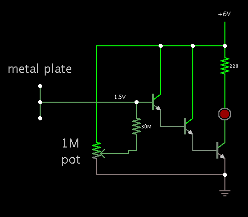
Given that I simply want to power a LED and I have therefore left out the relay and diodes, how would I modify this circuit to operate at 5-6V and with a small square of Al tape behind a piece of laminated paper?
The circuit does not really conform to an amplifier circuit that I can readily recognize and therefore know how to re-calculate the resistor values.
**broken link removed**
I probably should mention that it is designed for a touch activated feature in a shop window. So I don't really know whether or not the laminating plastic has any dielectric properties. I know the overhead projector sheets do.
- - - Updated - - -
Well I can measure about 1.3mV across the diode when I put my finger on the sensor, so the circuit appears to be working with 6V in, but not enough to turn on the LED.
When I take my finger of the sensor it drops to about 0.9mV within a second or two.

