Continue to Site

Welcome to EDAboard.com

Welcome to our site! EDAboard.com is an international Electronics Discussion Forum focused on EDA software, circuits, schematics, books, theory, papers, asic, pld, 8051, DSP, Network, RF, Analog Design, PCB, Service Manuals... and a whole lot more! To participate you need to register. Registration is free. Click here to register now.

How to wire / connect a off delay timer with a contactor ?

Status
Not open for further replies.

danishdeshmuk

Advanced Member level 1
Joined
Aug 17, 2011
Messages
426
Helped
35
Reputation
70
Reaction score
35
Trophy points
1,308
Activity points
4,001
How to wire / connect a off delay timer with a contactor ?
talking & asking about the electromechanical off delay timer

thanks
 
Last edited:

Can i turn on or turn off a 3 phase blower with an electromechanical off delay timer ?
 

It depends what your blower's on/off sequence is. If its a simple power switch, I assume you could just use a relay to toggle the power on and off with your timer.

Need more details...
 

its a 3 phase blower with a 3 phase contactor
 

well to be safe, you can put a relay on each phase... this would be the same as unplugging it when you turn all three relays off.
 

would you send/provide me the schematic to how to do that ?
 

How to wire / connect a off delay timer with a contactor ?
talking & asking about the electromechanical off delay timer

thanks

Yes you can switch contactor induction coil with simple switch or some control circuits. When you switch off coil of contactor all three and null on contactor is turned off, this depends from contactor which you are using, some contactors have different ports state from others. This induction coil is monophase and switch is simple.

**broken link removed**
 

would you provide me the schematic or circuit of it ?

so that i could grasp it ........
 

would you provide me the schematic or circuit of it ?

so that i could grasp it ........

In my post #8 you see three contactors, third on right of picture can be used for three phase system switching. Controling of contactor switch off/on is done over A1 and A2 ports on it. On A1 is connected phase (one) and on A2 is connected null. In other words A1 and A2 represent coil of contactor like at relays, but this coil working on 220V. Also there is contactors with coils on 12V, 24V, 48V,...

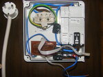
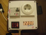
You can use any control circuit what you whish. Here is my example of switching timer device :

DSCF0117.JPG DSCF0128.JPG

I use mono phase mains outlet, if I need I can just replace that outlet with three phase and I can control three phase device. Timer is used to switch on some deivces each day at preset time, you can use any control circuit what you need.

- - - Updated - - -

Did you make Off Delay timer already ?
 

where is electromechanical off delay timers in these two pictures ?

I just wished to see the schematic ....... where the wires should be connected at the off delay timer .......... NO contacts would be used or NC contacts would be used ......... in order that the contactor just switched on or off whatever else want to achieve in the example ?
 

Circuit what I use is here, download my posted file all is in there "PCB V1.1.RAR" :

**broken link removed**

Also there is other circuits, this is just one.
 

Status
Not open for further replies.

Part and Inventory Search

Welcome to EDABoard.com

Sponsor

Back
Top