Continue to Site

Welcome to EDAboard.com

Welcome to our site! EDAboard.com is an international Electronics Discussion Forum focused on EDA software, circuits, schematics, books, theory, papers, asic, pld, 8051, DSP, Network, RF, Analog Design, PCB, Service Manuals... and a whole lot more! To participate you need to register. Registration is free. Click here to register now.

How to turn a TLC555 IC on with the output of a LM393?

itelec

Junior Member level 1
Joined
Jul 27, 2024
Messages
15
Helped
0
Reputation
0
Reaction score
0
Trophy points
1
Activity points
114
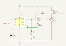
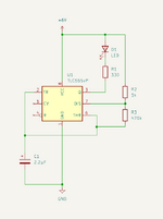
I made a TLC555 circuit for making a LED blink. It works fine but what I want is to make this led blink every time the output of an LM393 goes high and stop blinking when the output goes low for an alarm. I attached the screenshot of my timer circuit. I really hope you experts can help me solve this.
 

Attachments

  • screenshot.png
    screenshot.png
    21.8 KB · Views: 45
Do you see the R with a circle on pin4?
The circle means active low.
R means reset. When you connect your comparator logic levels to this , you will get what you want with Q out = low and LED on.
 
Last edited:
Thank you for your answer D.A.(Tony)Stewart.

I already tried connecting the output (pin 1) of the LM393 comparator to the reset (pin 4) of the TLC555 timer. While it easily toggles an LED, it doesn't control the 555's blinking. Instead, it just turns the LED on/off as the output pin goes high/low. I also tried using transistors on the comparator output, connected to the timer reset pin, but this resulted in the exact same behaviour.

1) What could be causing this behavior?
2) Are using the reset (pin 4) on the 555 timer the only option or could this be done another way?
 
Do you see the R with a circle on pin4?
The circle means active low.
R means reset. When you connect your comparator logic levels to this , you will get what you want with Q out = low and LED on.
When the output is low, the LED will be on steadily. Is that what you want, or do you want the LED off?
 
What I want to do:
  • When the LM393 output goes high => Start the 555 to make the LED pulse beweeen on/off according to the 555 circuit configuration.
  • When the LM393 output goes low => Turn off the LED entirely.
 
It sounds like you want to (or already did) configure the 555 as a pulse generator on free run, correct? Then you wish to disable it in response to a low incoming signal? You can add a 2-input AND gate to achieve this. The led lights when both inputs are high. The led is Off when either input is low. This makes the led flash.

AND gate one input pulled high or low to pass or block signal at other input.png
 
It sounds like you want to (or already did) configure the 555 as a pulse generator on free run, correct? Then you wish to disable it in response to a low incoming signal? You can add a 2-input AND gate to achieve this. The led lights when both inputs are high. The led is Off when either input is low. This makes the led flash.

View attachment 193449
No need for that. As Crutschow pointed out, just connect the LED from the output to ground instead of 6V.
 
No need for that. As Crutschow pointed out, just connect the LED from the output to ground instead of 6V.
I am not quite sure I understand. So the and gate isn't necessary? And the output (pin 3) of the 555 timer should go to ground instead (with the LED connected). Is that all needed to make it work? And the LM393 (pin 1) should go to the reset (pin 4), right?
--- Updated ---

Oh! I just saw the screenshot. Thank you so much! I need to try this :)
 
Ok, what happens now is:
  • When the LM393 output goes high => Turn off the LED entirely.
  • When the LM393 output goes low => Start the 555 to make the LED pulse beweeen on/off according to the 555 circuit configuration.
In other words. It's the opposite of what I am trying to do which is:
  • When the LM393 output goes high => Start the 555 to make the LED pulse beweeen on/off according to the 555 circuit configuration.
  • When the LM393 output goes low => Turn off the LED entirely.
Do you have any idea of how to solve that?
 
Either use a bjt to invert the LM393 signal

or the easier way:
* just interchange the (+) input with the (-) input of the LM393

Klaus
I didn't think of the inverting input. It did the trick. Now the circuit is working perfectly 👏
 
Hi,

a typical problem by (unexperienced) designers is to focus on the wrong signal/item.
When the LM393 output goes high =>

You obviously compare two signals. And the goal is
* IF (SignalA > SignalB) THEN ...

These are the INPUTS of the comparator.

But you gave us the task to work with the OUTPUT of your (forgive me the wording) semi elaborated comparator circuit.

****
A forum is meant that many people gain information from a discussion.
So here the recommendation for many people:

Give us the true intended function of a design:
[All necessary inputs] --> [expected solution / circuit] --> [expected output(s)]

Don´t give half designed solutions using intermediate signals:
[partly designed solution using inputs] --> [asking for this solution] --> [expected outputs]

***
The problem is, we professional designers try to solve really what you are asking for. If we are asked to use a comparator_OUTPUT signal, then we do this.
We expect you have a reason for your requirement to use it this way. Maybe the comparator is on a different circuit, that can not be altered, maybe the comparator output signal (in the given polarity) is used in another part of the circuit.

Klaus

Added:
Again thinking about the function. If all that the circuit needs to do is to blink a LED when one input signal is bigger than the other .. I guess I´d solve it with one comparator only (or 2 comparators in one package). So no need for an extra NE555.
 
Hi Klaus

The circuit is for a game with an alarm that triggers when two probes touch. Initially, I wanted a LED to turn on/off using a timer when the probes make contact. It's hard for me to explain, so I am trying to describe the issues I'm facing as well as I can. I am sorry if the examples are not detailed enough but I am trying to share as much as possible to allow others to learn from it as well.

The next step in my alarm circuit is to add a buzzer to the timer. Please see the attached screenshot of the current timer circuit with the buzzer.

This circuit works as expected but for some reason the buzzer makes a low click sound when it's supposed to be off (just like the LED). Does any of you know how to avoid this click sound?
 

Attachments

  • screenshot.png
    screenshot.png
    31.4 KB · Views: 17

LaTeX Commands Quick-Menu:

Part and Inventory Search

Welcome to EDABoard.com

Sponsor

Back
Top