ParmeetGhai
Newbie

How to SafeGuard against EMP/High Frequency Attacks, Forced System Reset and Force System Failure
IMPORTANT: I cannot use a microcontroller because of my living conditions whatever electronic that I own which contain firmware/software is vulnerable to re-programming attacks hence I can only work with hardware. no firmware/software.
I have the following circuit designed for a automated lock application.Can anyone think of conditions where the system can be compromised causing a power P-channel MOSFET to conduct and have a high power solenoid activated and also safe guards against EMP attacks, high frequency attacks, forced system resets and force system failure?
Any help will be greatly appreciated.
Note that the timing delay does not require precision. The circuit will be enclosed in stainless steel container hence offering some shielding. cannot use any micro controllers. Due to my living conditions any electronic gadget with software/firmware is vulnerable to re-programming/hacking hence only hardware can be used.
What is needed from the circuit is the following:
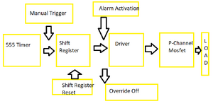
1) Manual trigger to activate the system otherwise the system remains idle.
2) A delay of >40 seconds after the system is activated.
3) After the delay is over then system activating a gate driver for a P-channel MOSFET.
4) P-channel MOSFET activates a high power solenoid for a lock and then gets disabled.
5) The initial trigger should never happen by itself unless manually triggered like in step 1.
6) Later an Alarm signal will trigger the power mosfet against
7) A override OFF signal then turns off the mosfet
Besides the solenoid, a stepper motor is also activated which is connected to a Scotch Yoke. it rotates in only one direction. which is why there is a need to turn on and off the mosfet twice. at 180 degree, it will activate the lock. at 360 degree it will unlock the lock.
The circuit should withstand:
1) Whole system resets.
2) Whole system failure.
3) High frequency/EMP attacks.
Preferred condition under such scenarios is that the P-channel MOSFET remains OFF thus preventing the lock from opening under default/reset/error conditions.
Typical use case:
1) After manual activation a delay of >40 seconds.
2) After the delay is over then gate driver activates P-channel MOSFET activating a high power solenoid lock.
3) The initial trigger turns off via optocoupler turning off the MOSFET.
4) The initial trigger never turns on unless its manually activated like in step 1.
5) A alarm activates the gate driver turning on the MOSFET.
6) The alarm is turned off via optocoupler which turns off the MOSFET.
First design:
It only used a Latch for initial trigger and a capacitor at the base of a NPN driver for delay. Some other design flaw made me consider the effects of a system reset and it turns out that the latch would trigger on by default under reset hence its omitted.
Second design:
The second design involved a 555 timer and a CD4017 (LTspice simulation attached). Everything works great except at system reset, the clock output from 555 shows a jitter which if not handled with a 1 µF capacitor leads to the system being triggered by default at system reset. If capacitor goes bad in case of a EMP attack then system is compromised hence this design was scrapped too.
Third/final design:
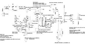
This one uses a 555 timer as well and a 74HC164 SIPO shift register replacing CD4017 and TC4429 as gate driver instead of a NPN (2N2222). the 74HC164 has a strong pull down at the input A and B thus requiring at least 9 V to be triggered and TC4429 has a built in Schmitt trigger which prevents noise and jitters. PS:I have used LTC1693-5 from analog.com as replacement for TC4429 because the model was giving out too much of a problem.
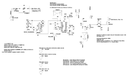
I have datasheets, LTspice schematics, LTspice libraries and symbols and screenshots of those schematics attached for reference here: https://drive.google.com/drive/folders/1ofFWJBdjE9LCo8oUX_3OSIO0Nte
 PBSTD?usp=sharing
IMPORTANT: I cannot use a microcontroller because of my living conditions whatever electronic that I own which contain firmware/software is vulnerable to re-programming attacks hence I can only work with hardware. no firmware/software.
I have the following circuit designed for a automated lock application.Can anyone think of conditions where the system can be compromised causing a power P-channel MOSFET to conduct and have a high power solenoid activated and also safe guards against EMP attacks, high frequency attacks, forced system resets and force system failure?
Any help will be greatly appreciated.
Note that the timing delay does not require precision. The circuit will be enclosed in stainless steel container hence offering some shielding. cannot use any micro controllers. Due to my living conditions any electronic gadget with software/firmware is vulnerable to re-programming/hacking hence only hardware can be used.
What is needed from the circuit is the following:
1) Manual trigger to activate the system otherwise the system remains idle.
2) A delay of >40 seconds after the system is activated.
3) After the delay is over then system activating a gate driver for a P-channel MOSFET.
4) P-channel MOSFET activates a high power solenoid for a lock and then gets disabled.
5) The initial trigger should never happen by itself unless manually triggered like in step 1.
6) Later an Alarm signal will trigger the power mosfet against
7) A override OFF signal then turns off the mosfet
Besides the solenoid, a stepper motor is also activated which is connected to a Scotch Yoke. it rotates in only one direction. which is why there is a need to turn on and off the mosfet twice. at 180 degree, it will activate the lock. at 360 degree it will unlock the lock.
The circuit should withstand:
1) Whole system resets.
2) Whole system failure.
3) High frequency/EMP attacks.
Preferred condition under such scenarios is that the P-channel MOSFET remains OFF thus preventing the lock from opening under default/reset/error conditions.
Typical use case:
1) After manual activation a delay of >40 seconds.
2) After the delay is over then gate driver activates P-channel MOSFET activating a high power solenoid lock.
3) The initial trigger turns off via optocoupler turning off the MOSFET.
4) The initial trigger never turns on unless its manually activated like in step 1.
5) A alarm activates the gate driver turning on the MOSFET.
6) The alarm is turned off via optocoupler which turns off the MOSFET.
First design:
It only used a Latch for initial trigger and a capacitor at the base of a NPN driver for delay. Some other design flaw made me consider the effects of a system reset and it turns out that the latch would trigger on by default under reset hence its omitted.
Second design:
The second design involved a 555 timer and a CD4017 (LTspice simulation attached). Everything works great except at system reset, the clock output from 555 shows a jitter which if not handled with a 1 µF capacitor leads to the system being triggered by default at system reset. If capacitor goes bad in case of a EMP attack then system is compromised hence this design was scrapped too.
Third/final design:
This one uses a 555 timer as well and a 74HC164 SIPO shift register replacing CD4017 and TC4429 as gate driver instead of a NPN (2N2222). the 74HC164 has a strong pull down at the input A and B thus requiring at least 9 V to be triggered and TC4429 has a built in Schmitt trigger which prevents noise and jitters. PS:I have used LTC1693-5 from analog.com as replacement for TC4429 because the model was giving out too much of a problem.
I have datasheets, LTspice schematics, LTspice libraries and symbols and screenshots of those schematics attached for reference here: https://drive.google.com/drive/folders/1ofFWJBdjE9LCo8oUX_3OSIO0Nte


