Continue to Site

Welcome to EDAboard.com

Welcome to our site! EDAboard.com is an international Electronics Discussion Forum focused on EDA software, circuits, schematics, books, theory, papers, asic, pld, 8051, DSP, Network, RF, Analog Design, PCB, Service Manuals... and a whole lot more! To participate you need to register. Registration is free. Click here to register now.

How to prove final value theorem?

Status
Not open for further replies.

v9260019

Member level 2
Member level 2
Joined
Jun 5, 2005
Messages
47
Helped
0
Reputation
0
Reaction score
0
Trophy points
1,286
Activity points
1,680
Final value theorem

Hello all
the final value theorem is defined by
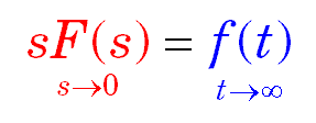
linit2.gif


the final value theorem is valid only if F(S) has poles only in the left half-plane and ,at most ,one pole at the origin. If F(S) has poles in the right half-plane or poles on the imaginary axis other than at the origin , the final value theorem is invalid~~~~~ how to prove this and why

thanks a lot
 

Re: Final value theorem

I am not sure but as far as i know, if F(S) has poles in the right half-plane or poles on the imaginary axis then the system described by F(s) is unstable(oscillating) thus there is no final(steady state value) and therefore the final value theorem is invalid.
 

Final value theorem

a Systen having poles in the right side is simply unstable. it does not have a settling value as u say in time domain or in Laplace it has no steady state value.or simply put

F(t)=(limt-->inf)f(t)
 

Re: Final value theorem

Perhaps you have forgotten the mathermatical equation of s=jw.
We know s->0 in s-domain is the same as saying t->∞ in time domain.
We know the function of a system is stable to infinite time.
Therefore if s is not zero, then jw is a non-zero.
To examine this, any pole given by (s-x) is represented in Z-Transform of Z=exp(jw). Now, if jw is a non-zero, then Z is not a one. Given a unit circle, for a stable system, Z must lie within the unit circle. If Z=1, it is likewise saying pole is placed along the Y-axis or more correctly called the Imaginary Axis of the Argand Diagram of a Root Locus Plot. Poles in the right-hand plane of the Argand Diagram is the same as having Z>1 outside the unit circle.
 

Status
Not open for further replies.

Part and Inventory Search

Welcome to EDABoard.com

Sponsor

Back
Top