Continue to Site

Welcome to EDAboard.com

Welcome to our site! EDAboard.com is an international Electronics Discussion Forum focused on EDA software, circuits, schematics, books, theory, papers, asic, pld, 8051, DSP, Network, RF, Analog Design, PCB, Service Manuals... and a whole lot more! To participate you need to register. Registration is free. Click here to register now.

[SOLVED] How to prevent latching with scr

Status
Not open for further replies.

Zak28

Advanced Member level 2
Joined
Aug 19, 2016
Messages
579
Helped
6
Reputation
12
Reaction score
6
Trophy points
18
Activity points
4,681
I understand an scr will latch if volts accross it do not reach 0 and I am unsure how to modify ciruit, or perhaps need an appropriate scr for latchless switching. Is it particular scr or improper topology which is causing latching?

bla.png
 

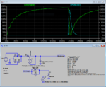
The object for this circuit is to dump cap into coil. The gate is pulsed 3x/second evenly spaced 8ms long. The latching persists regardless the amount of scrs I parallel up.
 
Last edited:

Hi,

An SCR is meant to latch
--> if you don't want latching function, then don't use an SCR.

Btw: SCR latching and SCR relaes is specified with "current" and not with "voltage".

Klaus
 
Is it particular scr or improper topology which is causing latching?
Clearly improper topology. Without the permanently connected rectifier circuit, the SCR is extinguished when the capacitor voltage falls below zero and the coil current commutates to the diode. Charge current must be interrupted during capacitor discharge time, e.g. by a second SCR. Or use MOSFET switch, as discussed in your previous thread: https://www.edaboard.com/showthread.php?377126-Misbehaving-thyristor-with-ltspice-simulation
 
  • Like
Reactions: Zak28

    Zak28

    Points: 2
    Helpful Answer Positive Rating
...current must be interrupted during capacitor discharge...

Infact I knew very well that's one way to remedy this, I tried to disconnect cap/coil with scr and could not run past 15% some reason.

blablabla.png

or is it really reversed? The trouble with fets is me being unable to find a single fet with an soa capable of handling volts/amps/duration of pulse.
 
Last edited:

Hi,

The trouble with fets is me being unable to find a single fet with an soa capable of handling volts/amps/duration of pulse.
This IMHO is not a problem of not_available_devices. It rather is a problem of how you do the search.

I don´t know your specificaitons, but if you don´t find a suitable MOSFET, you should try with IGBTs.

Klaus
 
  • Like
Reactions: Zak28

    Zak28

    Points: 2
    Helpful Answer Positive Rating
Clearly, if one SCR latches and stays on, adding a second in series with it will do just the same.

You need a device that turns off as well as turns on, *OR* if your pulse timing allows, use an SCR in the rectifier stage so you can use the alternating voltage to turn the incoming charge off so the original SCR resets. You might be able to add the new SCR after the diode bridge but before the capacitor to achieve that.

Brian.
 
  • Like
Reactions: Zak28

    Zak28

    Points: 2
    Helpful Answer Positive Rating
There are two obvious faults in the post #5 drawing.
1. The trigger source must be connected between gate and cathode, otherwise it's acting as SCR self-destroyer.
2. The second "charge control" SCR should be connected left of the capacitor.
 
  • Like
Reactions: Zak28

    Zak28

    Points: 2
    Helpful Answer Positive Rating
I believe the only viable option here is either disconnect cap from SCR whilst it charges or use a transistor (TRIACs yielded same result as scr). So I choose a IGBT IGW75N65H5XKSA1 and in the long run its cheaper than implementing a disconnect mechanism and its associated gate circuitry and also the IGBT is just about the same price as a MOSFET but can handle much more than a mosfet. Implementing a cap disconnect SCR will require me more soldering, heatsinks and oscillators. I'm pretty sure the IGBT I choose is up for the task, let me know if it isn't altho I highly doubt it is not capable.

View attachment IGW75N65H5XKSA1.pdf
 
Last edited:

A GTOSCR can be made to have a higher sustain current
by shunting one (or both) of the bases. A transistor in
that role could be smarter (like, shunt SCR gate once cap
has reached "low enough" voltage).

The other option might be to make the circuit resonant
so that discharging the cap ends up going below zero
long enough to get the SCR to quench. Maybe there are
some lessons from SCR-based power inverters?
 
  • Like
Reactions: Zak28

    Zak28

    Points: 2
    Helpful Answer Positive Rating
A GTOSCR can...

The only parts I found were hockey puck packaged. Large, heavy bulky expensive and probably exceed circuit demands by far. Unless I am unaware of non hockeypuck and reasonably priced (~$6 same as IGBT) parts, then they won't work for this.
 

The other option might be to make the circuit resonant so that discharging the cap ends up going below zero long enough to get the SCR to quench.
It's not possible by present design of the circuit.

I believe the only viable option here is either disconnect cap from SCR whilst it charges or use a transistor.
Unfortunately you didn't yet understand the problem of your circuit and the suggested correction. See how it works.

pulser2.PNG


I don't particularly say that SCR is the best option, or that the circuit should be exactly implemented this way. I would worry e.g. about the huge mains current peaks. The schematic is just there to show that a SCR solution is feasible.

GTO is more a theoretical possibility because small GTOs (10 - 50 A) aren't presently available. New devices will hard ly be launched because the technology has effectively been obsoleted by IGBT in their application field, except for the multi kV and kA DC power transmission range. One reason is the control effort, you need a negative turn-off gate current > instantaneous anode current.
 

Attachments

  • pulser2.zip
    1.4 KB · Views: 141
  • Like
Reactions: Zak28

    Zak28

    Points: 2
    Helpful Answer Positive Rating
It's not possible by present design of the circuit...

Did you mean to say using IGBT inplace of SCR for original iteration wont work?
 

Did you mean to say using IGBT inplace of SCR for original iteration wont work?
Hardly. Just read, which part is the answer referring to? IGBT or SCR? I have written about transistor switch (MOSFET/IGBT) option before.
 
  • Like
Reactions: Zak28

    Zak28

    Points: 2
    Helpful Answer Positive Rating
It might be possible to use a second SCR in a commutating design but the complexity probably isn't worth it. You shut off the present SCR by charging a capacitor to some voltage then discharge it with reversed polarity across the SCR using a second device. The theory is that reversing the polarity effectively drops it's current to zero and stops it conducting. It requires more control signals, more components and critical timing so it probably isn't a solution worth considering.

Brian.
 
  • Like
Reactions: Zak28

    Zak28

    Points: 2
    Helpful Answer Positive Rating
...the huge mains current peaks...

I am uncertain whether its best to serially attach a few power resistors or an inductor to limit rms current to acceptable levels (leave some margin for other stuff on residential circuit so as to not trip a breaker) I am unaware for other methods to limit mains current. I'd really appreciate suggestions for this issue especially if the 2 things I am considering aren't ideal.
 

Inductor would be preferred.

I agree because inductor dissipates less power (mills of resistance) and stores it as a mini reservoir, however after exhaustive searching the only "inductors" I found were chokes and I would need to connect them serially so as to get as much inductance as I can get. They are pricey because they are to handle a considerable amount of current and I rather get buy a bunch of power resistors than wind my own coil (perhaps I will end up winding one anyways) I would like to be pleasantly surprised here if anybody can show a part which is 15-40mH below $11 which can pass ~10-15amps RMS - this would be greatly appreciated. Altho I have a bunch of 12awg wire around the house and I guess I can take a mot apart, but Id still rather buy a coil.
 
Last edited:

If this is a pulsed power low rep rate gizmo as initially it
seemed, maybe you don't need to be concerned with RMS
current carrying capacity. Build it and blow it up and learn
(if you survive; remote triggering is much less sexy but
much more important to get right).

Now here's a pertinent thought. You seem to be partly
stymied by wanting high current in a high voltage switch
and when you want the upper right corner you are
looking at upper right pricing@qty and lower left number
of options. So, what about paralleling C-switch strings
using high voltage, N times the tolerable Ron devices?
Large value caps are sort of volumetric par for C*V
so probably costs you nothing much in that aspect.
Gang trigger them all and figure current sharing will
be good enough since the inductor's in charge. A
massively parallel scheme might even be fitted around
other features, perhaps optimizing the delivery of the
pulse to whatever the business end of the gizmo may
be.

Paralleling the caps parallel-reduces the effect of their
ESL (which can be heinous for large surplus electrolytics)
and that can be a major bonus. See what your caps' SRF
is and how that compares to the pulse harmonics you are
hoping to see (risetime can be called a quarter cycle).
And smaller caps tend to have smaller ESL to begin with.
 
Last edited:
  • Like
Reactions: Zak28

    Zak28

    Points: 2
    Helpful Answer Positive Rating
To reduce the peak current effectively, you need an inductor of 10 to 50 mH. It must be designed not to saturate at peak current, ends up with gapped laminated steel core. Not sure if you find a suitable choke of the shelf, it must be probably custom made.
 
  • Like
Reactions: Zak28

    Zak28

    Points: 2
    Helpful Answer Positive Rating
Status
Not open for further replies.

Part and Inventory Search

Welcome to EDABoard.com

Sponsor

Back
Top