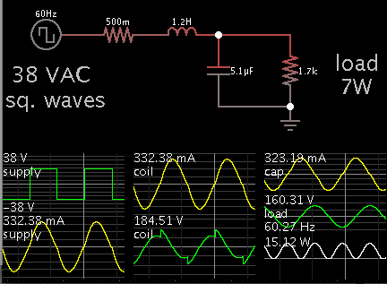
What value L and C could I use to get a sinewave for a 8W inductive load????
We can calculate a value for C which will resonate at 60 Hz with an inductor L. This is the action which obtains a sine wave.
However if the load is an inductor... Then it means the resistance is small in the loop, and this will encourage resonant oscillations to build. The amplitude can climb to many times the supply voltage. Adjustments will be necessary.
Going ahead with the formulae...
An 8W load, at 120VAC, calculates to 67mA, and impedance 1800 ohms.
The inductive load needs to be 1800 ohms reactive impedance, at 60 Hz.
Using the formula X = 2 Pi F L...
The inductor is 4.8 H.
The capacitor will also be 1800 ohms reactive impedance at 60 Hz.
Using the formula X = 1 / (2 Pi F C)...
Capacitor value is 1.47 uF.
As a value for R, I guessed 10 ohms.
Running in simulation, the voltage climbed high.
I experimented with the supply voltage.
I found I had to reduce the supply amplitude to 1.7V.
Theoretically, this eventually builds (after many cycles) to a 120 VAC sinewave across the 4.8 H inductive load.
The target was 67 mA AC current. Looking at the 10 ohms resistance, it turns out that only .67 VAC is sufficient to send 67 mA through 10 ohms. The resonating action by itself does not consume power, therefore the simulated action leads to large voltage swings.
However the simulation is done with ideal components. Real components are less than 100% efficient.


