Continue to Site

Welcome to EDAboard.com

Welcome to our site! EDAboard.com is an international Electronics Discussion Forum focused on EDA software, circuits, schematics, books, theory, papers, asic, pld, 8051, DSP, Network, RF, Analog Design, PCB, Service Manuals... and a whole lot more! To participate you need to register. Registration is free. Click here to register now.

how to make DP flash every sec in 2-digit 7-segments without separation of track

Status
Not open for further replies.

saramah

Member level 3
Member level 3
Joined
Apr 25, 2018
Messages
64
Helped
0
Reputation
0
Reaction score
0
Trophy points
6
Activity points
689
In multiplxing of 2-digit 7-segments disp and to get all two dotpoint(dp) in vetically (i,e. 2nd digit is inverted at 180 degree) pin swaping is made each others.
Further that two digit were bought alongwith pre-made standrad pcb. And the pcb is Common Anode and dot track of its is also interconnected with common point anode.
My question is, I want to make that two DPs flash together at every second without cutting(disconnecting) the tack from common which is alredy connceted with CA point in fabricated pcb??
The xc8, pic887 code is here,

Code:
//***Define the signal pins of all four displays***//
#define s1 RC0
#define s2 RC1


void main()
{
unsigned int e,f,g,h; //just variables
int i = 0; //the 2-digit value that is to be displayed
int flag =0; //for creating delay

unsigned int seg[]={0XC0, //Hex value to display the number 0
                    0XF9, //Hex value to display the number 1
                    0XA4, //Hex value to display the number 2
                    0XB0, //Hex value to display the number 3
                    0X99, //Hex value to display the number 4
                    0X92, //Hex value to display the number 5
                    0X82, //Hex value to display the number 6
                    0XF8, //Hex value to display the number 7
                    0X80, //Hex value to display the number 8
                    0X90  //Hex value to display the number 9
                   }; // dot not incoporated here


//*****I/O Configuration****//
TRISC=0X00;
TRISD=0x00;


PORTC=0XFF; 


#define _XTAL_FREQ 20000000

while(1)
{
    
  //***Splitting "i" into four digits***//  

e=d%10; //2nd digit is saved here
f=d/10;
g=f%10; //1st digit is saved here
h=f/10;


PORTD=seg[g];s1=0; //Turn ON display 1 and print 4th digit
__delay_ms(5);s1=1;     //Turn OFF display 1 after 5ms delay
PORTD=seg[e];s2=0; //Turn ON display 2 and print 3rd digit
__delay_ms(5);s2=1;     //Turn OFF display 2 after 5ms delay


if(flag>=10) //wait 
{
    i++;flag=0; 
}
flag++; //increment flag for each flash
}
}

What is understand, If dot's logic is considerd here in seg[] array the it will light up always. as per my openion, my expection can only be fulfil if i cut the track from fabricated pcb from ca track.
Your suggestion please??
tnk u...
 

I think you are right. The DP are on different digits and your code only enables one digit at a time. That means it is impossible to make both DP light at the same time.
It may be possible for them to appear to be on simultaneously by enabling the DP on both digits, something like:
Code:
(pseudo code)
if (DP_On == TRUE) seg[ ] &= DP;
else seg[ ] |= ~DP;
where DP_On is the signal that enables the dots. You would have to add the dot to the seg[] array values.

Brian.
 

... or map the DP in the above character map, which in this case would double in size; half with the decimal point ON, and the other half with the decimal point OFF.
 

@betwixt >>
Thats mean u are asking to cut the track of dots point.

@andre_teprom>>
Will u please explain more specifically..
 

or map the DP in the above character map, which in this case would double in size; half with the decimal point ON, and the other half with the decimal point OFF.
I was thinking of a different approach. I assume there is a connection from the MCU to the DP in the same was as all the segments. Regardless of what is in the segment table, there would be one MCU pin feeding the DP segment. All you have to do is generate a 'flash' signal and feed that signal to the pin driving the DP. If you have the dot paralleled across more than two digits, for example if the dots are between two digit hours and two digit minutes, then only send the signal tot he MCU pin while the middle two digit drives are active. Doing it that way (logic AND the flash and DP drive) means you can still keep the same segment table and no tracks have to be cut.

Brian.
 

@andre_teprom>>
Will u please explain more specifically..

@saramah
Will you show your schematic ?

- - - Updated - - -

I assume there is a connection from the MCU to the DP in the same was as all the segments

I was thinking of multiplexed connection, perhapps the mapping approach would solve this way, but we'll expect OP give little more details.
 

Sorry to responce in delay!
@andre_teprom
HTML:
Will you show your schematic ?
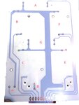
The segment-pcb is here attached here. Pl note I am using multiplx technique here. FINAL1.jpg
From the schematic,
As desire type is CA type and that is why COMMON track is Anode-Control-Track and others all respective Cathod-Control-Tracks. And Further, DP-Anode is under COMMON track & DP-Cathode separate.
I was asking should i dis-continute the track of DP-Anode from COMMON to blink the two DP of two Digits altogether.

@betwixt:Once chk the pcb and could u explain more elaborately plaese.


tnx all of you..
 

To display DP, you should toggle highest bit for your digit. i.e. 8. would be 0X00 (0B00000000) as oposed to 8 which is 0X80 (0B10000000), and so on for each digit.

As betwixt showed in his pseudo code.
 

@saramah
Will you show your schematic ?
From the schematic, (...)

You know that there is no schematic there. Also, you are surely aware that spenting little effort to make things clearer decreases the amount of people willing to help, few ones will make a reverse engineering in the above pcb board layout to decipher the connections, I`m out, good luck.
 

The PCB only shows one digit. It is how more than one digit is multiplexed that we need to know. Please show us a schematic.

Brian.
 

Status
Not open for further replies.

Similar threads

Part and Inventory Search

Welcome to EDABoard.com

Sponsor

Back
Top