Continue to Site

Welcome to EDAboard.com

Welcome to our site! EDAboard.com is an international Electronics Discussion Forum focused on EDA software, circuits, schematics, books, theory, papers, asic, pld, 8051, DSP, Network, RF, Analog Design, PCB, Service Manuals... and a whole lot more! To participate you need to register. Registration is free. Click here to register now.

How to make a reference voltage with bgr?

Status
Not open for further replies.

goatmxj666

Member level 3
Member level 3
Joined
Mar 5, 2023
Messages
55
Helped
0
Reputation
0
Reaction score
1
Trophy points
8
Activity points
540
Hello!

I studied the BGR circuit that is insensitive to PVT variations and made a schematic.

I understand that output voltage is 1.2V,

but If my circuit needs voltage like 0.6V or 2.5V as a reference voltage, how do I make these voltages?

I tried to make a reference voltage by using resistor divider with bgr.

If I do that, I think the characteristics of bgr, (which are insensitive to pvt variation) will change to be sensitive again.

But I've seen in several papers making the reference voltage with a resistive divider or a diode connected MOSFET.

Any help would be appreciated.
 

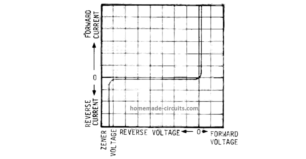
5V zener diode is known to have neutral response to temperature. Lesser volt ratings are negative temperature coefficient. Greater volt ratings are positive.

See link below. Graph appears 1/5 of the way down page:


Hello!

I studied the BGR circuit that is insensitive to PVT variations and made a schematic.

I understand that output voltage is 1.2V,

but If my circuit needs voltage like 0.6V or 2.5V as a reference voltage, how do I make these voltages?

I tried to make a reference voltage by using resistor divider with bgr.

If I do that, I think the characteristics of bgr, (which are insensitive to pvt variation) will change to be sensitive again.

But I've seen in several papers making the reference voltage with a resistive divider or a diode connected MOSFET.

Any help would be appreciated.
A resistive divider will not add temperature sensitivity to your circuit, since the output voltage depends on the resistance ratio, which does not depend on temperature (or depends weakly). You can also make BGR circuits on several diodes, which can give a multiple of the BandGap voltage (for example two diodes give you a voltage about 2.4 - 2.5 V) (Attached a picture from the Razavi book)
 

Attachments

  • Screenshot_1.png
    Screenshot_1.png
    30.9 KB · Views: 169

Since you are looking for larger voltages like 2.5V, I suppose, your Vcc/Vdd is higher than 2.5V
With that in mind, you can go for a "Current Mode" BGR circuit (Banba et al)
1678769283579.png


Here the Current through R3 is a Vbg/R current. Basically, MP2 carries a current of VPTAT/R0 + VCTAT/R2.
The final Vref voltage is R3*(Vptat/R0 + Vctat/R2)

Adjust R0 and R1/R2 to get the least voltage variation. And adjust R3 to get the voltage you want. It can be any value and is not required to be 1.2V.
You can also split R3 into segments and tap different points to get different voltages.

With this method, you are not adding additional buffers which bring their own variations. As long as all the component are matched, you will get a very got performance.
 

Creating a reference voltage with a BGR 500 is relatively simple, and can be done in a few steps.
First, connect the BGR 500 to a power supply. Make sure the power supply is set to the desired voltage. If a higher voltage is needed, a voltage regulator can be used to reduce the voltage.
Next, connect the BGR 500 to the reference voltage input of the circuit. Make sure the connection is secure and insulated. Now, turn on the power supply. The BGR 500 should begin to regulate the voltage output to the reference voltage set by the power supply.
Finally, the reference voltage can be tested by connecting a multimeter to the output of the BGR 500. This should show the voltage output to be equal to the reference voltage set by the power supply. By following these steps, a reference voltage can easily be created with a BGR 500. The BGR 500's simple design and easy to use features make it an ideal choice for creating a reference voltage.
Hello!

I studied the BGR circuit that is insensitive to PVT variations and made a schematic.

I understand that output voltage is 1.2V,

but If my circuit needs voltage like 0.6V or 2.5V as a reference voltage, how do I make these voltages?

I tried to make a reference voltage by using resistor divider with bgr.

If I do that, I think the characteristics of bgr, (which are insensitive to pvt variation) will change to be sensitive again.

But I've seen in several papers making the reference voltage with a resistive divider or a diode connected MOSFET.

Any help would be appreciated.
 

Status
Not open for further replies.

Similar threads

Part and Inventory Search

Welcome to EDABoard.com

Sponsor

Back
Top