How to limit the maximum output power in this circuit ?
- Thread starter hm_fa_da
- Start date
- Status
- Not open for further replies.


- Joined
- Jul 4, 2009
- Messages
- 16,643
- Helped
- 5,158
- Reputation
- 10,349
- Reaction score
- 5,250
- Trophy points
- 1,393
- Location
- Aberdyfi, West Wales, UK
- Activity points
- 140,826
Your schematic can be read left to right or right to left so the question is confusing.
You need to tell us what voltage is being applied. If the voltage source is through the fuse it has to be less than 9V or else the Zener diode will conduct and blow the fuse.
If you mean 'Po' is the maximum power you can draw from the source and the output is from the fuse, we still need to know the voltage so the value of R can take into account any current through the diode.
Brian.

hm_fa_da
Full Member level 5

Thanks for your reply, I sent the corrected schematic here:

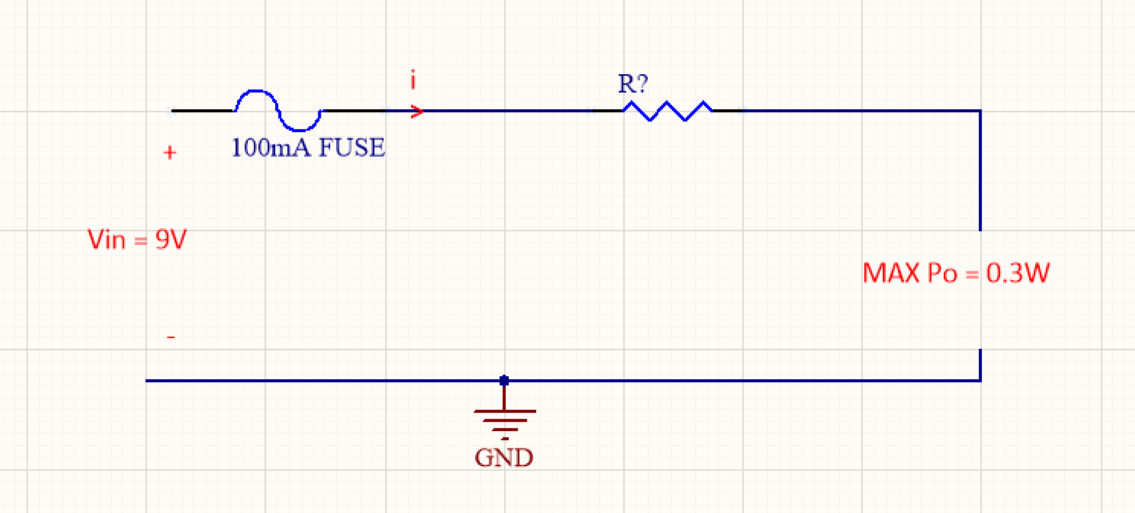
Assume Vin is 9V (Zener was just a protection for higher voltages - so in my question it has no role) , The schematic input is in left side, output right side. I mean by MAX Po:
I want to set a value for R so that any load connected to Po not be able to draw more than 0.3W ...
Assume Vin is 9V (Zener was just a protection for higher voltages - so in my question it has no role) , The schematic input is in left side, output right side. I mean by MAX Po:
I want to set a value for R so that any load connected to Po not be able to draw more than 0.3W ...
- Joined
- Jan 22, 2008
- Messages
- 53,695
- Helped
- 14,811
- Reputation
- 29,919
- Reaction score
- 14,437
- Trophy points
- 1,393
- Location
- Bochum, Germany
- Activity points
- 303,571
The schematic in post #1 looks like the principle circuit of a zener barrier for intrinsic safety. Its design isn't based on nominal values for e.g. zener voltage or fuse current. You rather need to consider maximal values that can occur under certain defined conditions, e.g. maximal input voltage.
Presumed, fuse and zener diode (actually a threefold parallel circuit according to safety rules) are chosen so, that the fuse protects the zener under the given condtions, e.g. maximal input voltage of 250 V, you get an Vo value (maximal open circuit output) of e.g. 10.5 V. Then R is obtained by impedance matching condition, Po = (Vo/2)²/R. In this case about 92 ohms, a higher nominal value e.g. 100 ohms has to be chosen.
Refer to data sheets of approved zener barriers and safety standards for details.
Impedance matching condition applies also to the post #3 circuit. The circuit doesn't work for intrinsic safety unless Vin is safely limited to 9V. The fuse is useless then, because the resistor already limits the current to a lower value.
Presumed, fuse and zener diode (actually a threefold parallel circuit according to safety rules) are chosen so, that the fuse protects the zener under the given condtions, e.g. maximal input voltage of 250 V, you get an Vo value (maximal open circuit output) of e.g. 10.5 V. Then R is obtained by impedance matching condition, Po = (Vo/2)²/R. In this case about 92 ohms, a higher nominal value e.g. 100 ohms has to be chosen.
Refer to data sheets of approved zener barriers and safety standards for details.
--- Updated ---
Impedance matching condition applies also to the post #3 circuit. The circuit doesn't work for intrinsic safety unless Vin is safely limited to 9V. The fuse is useless then, because the resistor already limits the current to a lower value.
Last edited:
hm_fa_da
Full Member level 5
The schematic in post #1 looks like the principle circuit of a zener barrier for intrinsic safety. Its design isn't based on nominal values for e.g. zener voltage or fuse current. You rather need to consider maximal values that can occur under certain defined conditions, e.g. maximal input voltage.
Presumed, fuse and zener diode (actually a threefold parallel circuit according to safety rules) are chosen so, that the fuse protects the zener under the given condtions, e.g. maximal input voltage of 250 V, you get an Vo value (maximal open circuit output) of e.g. 10.5 V. Then R is obtained by impedance matching condition, Po = (Vo/2)²/R. In this case about 92 ohms, a higher nominal value e.g. 100 ohms has to be chosen.
Refer to data sheets of approved zener barriers and safety standards for details.
--- Updated ---
Impedance matching condition applies also to the post #3 circuit. The circuit doesn't work for intrinsic safety unless Vin is safely limited to 9V. The fuse is useless then, because the resistor already limits the current to a lower value.
Thanks for your reply, I was just looking for this formula "Po = (Vo/2)²/R" which you mentioned, so for 9V Vin, R would be 67.5 ohms.
However, there is a point, the current when calculating maximum Po can't exceed Fuse Amperage, in the schematic i sent, considering 67.5ohms for R, the maximum current in MAX Po would be = 9/(67.5+67.5) = 0.066A ( which is less than Fuse current). so no problem.
Example 2:
But in same schematic, assume 9V as input voltage, Max Po = 0.7W, R would be => 0.7 = (9/2)^2 /R => R = 28.92 ohms.
but the maximum current in MAX Po condition would be : 9/(28.92+28.92) = 0.155A which is more than Fuse current (0.1A) and can't happen so here we see a limitation of Fuse current affecting result.
I calculated the R in the second example in this way:
MAX Total Pout = 9*0.1 = 0.9W I want to decrease it by 0.2W to achieve max 0.7W in Po, so R*I^2=0.2 => R*(0.01) = 0.2 => R = 20 ohms.
As I'm looking for the minimum value for R, 20 ohms is less that 28.92 ohms and still max Po would be 0.7W .
Last edited:
Easy peasy
Advanced Member level 6
To limit the Pout to 0.3 watt, use the max power transfer theorem, thus R? must = Rload when Rload is drawing 0.3 watt.
For 9V this is 67.57 ohms, as when we have R? = Rload = 67.57 ohms, the current = 66.67mA, and the power in each = 0.3 watt
If you take Rload higher or lower, it's power will be less. ( even tho' the current will be higher in the latter case ).
you're welcome
For 9V this is 67.57 ohms, as when we have R? = Rload = 67.57 ohms, the current = 66.67mA, and the power in each = 0.3 watt
If you take Rload higher or lower, it's power will be less. ( even tho' the current will be higher in the latter case ).
you're welcome
- Status
- Not open for further replies.
Similar threads
-
Help me understand this input power supply circuitry
- Started by alexv1n
- Replies: 8
-
-
transistor limiting current on the output load problem in simulation
- Started by yefj
- Replies: 1
-
controlling mosfet biasing directly in the circuit question
- Started by yefj
- Replies: 2
-