Continue to Site

Welcome to EDAboard.com

Welcome to our site! EDAboard.com is an international Electronics Discussion Forum focused on EDA software, circuits, schematics, books, theory, papers, asic, pld, 8051, DSP, Network, RF, Analog Design, PCB, Service Manuals... and a whole lot more! To participate you need to register. Registration is free. Click here to register now.

How to layout Parallel components

kobi731

Newbie
Newbie level 2
Joined
Aug 15, 2024
Messages
2
Helped
0
Reputation
0
Reaction score
0
Trophy points
1
Activity points
23
Hello,

I have a very simple question that I haven't found an answer to it anywhere online.

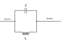
If I want to design a wideband filter—or any other circuit— that it have parallel components (like in the image below) as a electrical schematic. And I'm using lumped elements, how should I implement it in the layout for achieve good and wideband performance.

I.E like using ADS?

What I'm currently doing isn’t working at all.
maybe use Wilkinson divider but it make it too complicated.
 

Attachments

  • 1723712194213.png
    1723712194213.png
    37.8 KB · Views: 39
Last edited:
Your schematic is a bandstop network. If you want to make a passband, try other ways to arrange C&L network:
* Put C & L in series.
* Or connect LC tank to ground.

As a general thing, select C & L values to accommodate the amount of current available.
L:C ratio governs steepness of your rolloff curve.

Greater C is associated with Low frequencies, lesser impedance.
XC=1/(2πfC)

Greater L is associated with Low Frequency, greater impedance.
XL=2πfL

Example, center frequency is 25 MHz or so:
bandpass 25 MHz LC tank 3 various LC ratios.png
 
Thank you very much,
I indeed can find different topology, but I wanna to apply the parallel topology, for learning how to make a high frequency microstrip parallels connections.
Using tee junction? Round junction? two Wilkinson's?
 

LaTeX Commands Quick-Menu:

Part and Inventory Search

Welcome to EDABoard.com

Sponsor

Back
Top