Continue to Site

Welcome to EDAboard.com

Welcome to our site! EDAboard.com is an international Electronics Discussion Forum focused on EDA software, circuits, schematics, books, theory, papers, asic, pld, 8051, DSP, Network, RF, Analog Design, PCB, Service Manuals... and a whole lot more! To participate you need to register. Registration is free. Click here to register now.

[SOLVED] How to layout an unusual crystal

Status
Not open for further replies.

Alper özel

Member level 1
Member level 1
Joined
Feb 28, 2015
Messages
40
Helped
0
Reputation
0
Reaction score
0
Trophy points
6
Location
Turkey / Scotland
Activity points
487
Hi, I need a 32768 Hz crystal and I found only one crystal which covers my requirements. However, this one is a bit strange. Please look at the following picture:
1.png
You see, the crystal is between pin 1 and 4. But what about the other shorted pins 2 and 3? Why do I need them, What do I have to do with them? How to prepare a layout for this type of quartz? You can find the component here: https://www.digikey.com/product-detail/en/CM200C32768HZFT/300-8742-1-ND/2108134

Thanks.
 

You don't need to make use of pins 2 and 3, but you could use them as a bridge.
 
Thanks for reply. What do you mean by bridge? If I have a signal route for instance, can I accross through these pins? Would not it damages the signal integrity, interfere with sensitive quartz oscillation?
 

What do you mean by bridge? If I have a signal route for instance, can I accross through these pins?
Yes.

Would not it damages the signal integrity, interfere with sensitive quartz oscillation?
It's far enough from the Xtal - if you don't cross ac ampères ;-). But if you aren't sure, just leave these pins untouched or connect them to GND.
 
Thank you I got it. It seems like unnecessarily occupying of area to me though. If the component might have been designed to be smaller, it is so pointless. Thank you again.
 

Just consider that there's a cyclindrical can inside the SMD plastic case, containing the tuning fork crystal. It's a classical watch crystal form factor which is still frequently used. But you can get much smaller watch crystals if you are willing to pay a few cent more, e.g. https://www.abracon.com/Resonators/ABS05.pdf Larger cystals have probably a better specification.

The traces between crystal and oscillator circuit (RTC chip, processor...) should be at sufficient distance from possible interfering signals, otherwise the clock accuracy might be a affected.
 
I suspect it is the base of the tuning fork, so don't interfere with those pins.

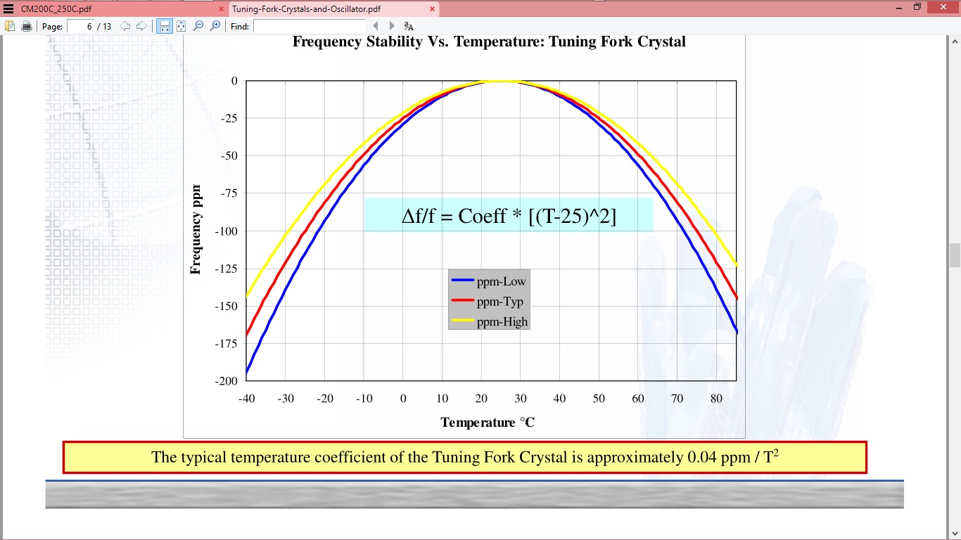
this 5 ppm tolerance is only good if you are at 25'C +/-5 which is also the bottom flat part of a parabolic curve.

If you need 5ppm but wanted to use a smaller part, you might be able to have select on test process to get better than 5ppm with a few pf parts.
 
Once the datasheet do not make any mention in regard to these 2 pins, I would dare to say that is not totally unthinkable that internally may be somehow connected to the chip die, therefore should be prudent connect them to the circuit ground.
 
therefore should be prudent connect them to the circuit ground.
I tend to agree, however if the datasheet specifies "do no connect" I would follow the specification in a first order.
 

If you read the data sheet as FvM has pointed out it says DO NOT CONNECT!!!!!!! please read data sheets correctly it will save you time and hassle in the future, attention to detail is the key.
 
It seems like unnecessarily occupying of area to me though. If the component might have been designed to be smaller, it is so pointless.
The additional pads add structural mechanical strength when the part is mounted on a PCB.
 
actually, I did see the warning: Do not connect to external. However, I was not sure if I should connect them to GND or leave it open or something else. I see know, these are just exist due to the symmetry and strong surface mounting. I think they warn you to not connect extarnal because they want to prevent you to confuse and connect load capacitors to wrong pins. I might be wrong but it looks like most logical explanation to me. Thanks to everyone.
 

this 5 ppm tolerance is only good if you are at 25'C +/-5 which is also the bottom flat part of a parabolic curve.

If you need 5ppm but wanted to use a smaller part, you might be able to have select on test process to get better than 5ppm with a few pf parts.

Digikey hasn't listed the specs properly... 5ppm is the frequency stability, not the tolerance.
 

Digikey hasn't listed the specs properly... 5ppm is the frequency stability, not the tolerance.

I think Digikey specified the equivalent 5ppm error over a +/-5 'C window around 25'C ... maybe ?
If that is true, then it can be called Stability.
Tolerance is always the room temp initial error.

**broken link removed**

Tolerance is 20ppm
Stability is - 0.034±0.006ppm/℃² from the turnover temperature which is 25+/-5'C with an operating temp over - 40℃~ + 85℃.
... meaning the error increases with square of temp from the midpoint.

So accuracy after Tolerance error is nulled, over +/-5'C is much lower and perhaps within 5ppm
But then aging is another factor of 1 or 2 ppm per year.

9900169400_1440027038.jpg


This is an inverted parabolic curve so the maximum frequency is at the turnover temp where 20 ppm is the initial tolerance which can be corrected with a tuning cap, varicap or select on test caps.

Who knows where Digikey got there room temp tolerance value of 5ppm from!
 

Status
Not open for further replies.

Part and Inventory Search

Welcome to EDABoard.com

Sponsor

Back
Top