Continue to Site

Welcome to EDAboard.com

Welcome to our site! EDAboard.com is an international Electronics Discussion Forum focused on EDA software, circuits, schematics, books, theory, papers, asic, pld, 8051, DSP, Network, RF, Analog Design, PCB, Service Manuals... and a whole lot more! To participate you need to register. Registration is free. Click here to register now.

[SOLVED] How to implement a LPF with DC blocking?

Status
Not open for further replies.

tony_lth

Advanced Member level 5
Joined
Jul 28, 2010
Messages
2,098
Helped
377
Reputation
756
Reaction score
369
Trophy points
1,363
Location
Beijing
Activity points
12,727
I need a component, which should be LPF, and it should be DC-blocking.
Bead: LPF, but DC pass through.
Capacitor: DC-blocking, but is HPF.
Is my requiment possible in one component?

- - - Updated - - -

My LPF should be:
Pass band: 100Hz~20KHz, audio
Stopband: >100MHz
 

Hi,

Add another series C.

Klaus
 
I almost agreed but now see "Pass band: 100Hz" - ...
Ouch. They make 100uF (and larger) ceramic caps. I'm not sure where they fall apart or what the audio distortion would be.
 
since it is audio, I would assume the system impedance is not 50 ohms. So just use a series ceramic 22 uF capacitor with your inductor "bead" or a purchased SMT lowpass filter, such as this one:

**broken link removed**

or even just follow the series 22 uf with a 100 ohm series and then 0.22 uF shunt cap
 
Using several tens uF ceramic caps is OK to earpiece.
The original configuration is bead + earpiece from audio chip output pin, but sometimes the earpiece may be burnt coil.
So someone guess the issue is caused by DC, so they decided to series caps.
But after my simulation, there is self-oscillation @freq<10Hz with cap+bead+earpiece config.
And the verified result is the burnt coil rate is much up after series a cap.
My simulation using 50 ohms termination, and got dB(S11)>0 @freq<10Hz.
When I set port to 500 ohms, dB(S11)<0 but dB(S21)>0 @ freq<10Hz.
The result is werid because there are only passive components L/C in the path.
So I guess originally there is some very low freq self-osc there, and series cap worse that situation. What do you think?

- - - Updated - - -

I think dB(S21)>0 @freq<10Hz is normal due to interpolation of the simulation model.
But dB(S11)>0 is abnormal, right?
 

IMy LPF should be:
Pass band: 100Hz~20KHz, audio
Stopband: >100MHz

Since 100 MHz comes into the picture, could this be due to self-resonance in your coil?

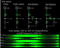
For bandpass in the audio range, circuits #3 and 4 below may suit your purpose, with no need for an inductor.


Capacitor values need to be adjusted up or down, to combine with resistance in neighboring components, to create the desired filter response.
 
Great, BradtheRad, that is my needed.
Many thanks.
 

Status
Not open for further replies.

Part and Inventory Search

Welcome to EDABoard.com

Sponsor

Back
Top