Continue to Site

Welcome to EDAboard.com

Welcome to our site! EDAboard.com is an international Electronics Discussion Forum focused on EDA software, circuits, schematics, books, theory, papers, asic, pld, 8051, DSP, Network, RF, Analog Design, PCB, Service Manuals... and a whole lot more! To participate you need to register. Registration is free. Click here to register now.

How to identify number of phases?

Status
Not open for further replies.

AutoNub

Newbie level 3
Newbie level 3
Joined
Sep 20, 2011
Messages
3
Helped
0
Reputation
0
Reaction score
0
Trophy points
1,281
Activity points
1,298
Hello. I look at various schematics all day long at work and I'm wondering, what is the fastest way to identify whether a particular system is 3 phase or 2 phase or single phase based on solely a schematic? They all seem to start with an A, B, C recepticle (3 lines).

Thanks!
 

Hi,
Can you upload a portion of the diagram where it says A,B and C lines for a better explanation on your RELATED diagram.
 

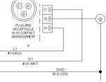
Line, Neutral, Ground.JPG


The above is a quick partial example...
 

That image shows Line (L1), Neutral (N1), and Ground (GND) so it is single phase.
 

If one of each is an indication of one phase, what would be an indication of multiple phases? Be specific.

Thanks.
 

If I saw L1, L2, L3, and GND I would expect 3 phase delta. L1, L2, L3 ,N1 and GND is likely 3 phase star. L1, L2 for 2 phase. N1 implies a power return. GND may conduct power if it is alone, or it is likely just for safety if it accompanies N1.

Note there are some 3 phase systems with one corner grounded, so it could only have L1, L2, and GND. You may find this in aircraft to reduce weight, but also in locomotives, ships, and anywhere poeple are too cheap to pay for decent copper.
 

Status
Not open for further replies.

Similar threads

Part and Inventory Search

Welcome to EDABoard.com

Sponsor

Back
Top