Continue to Site

Welcome to EDAboard.com

Welcome to our site! EDAboard.com is an international Electronics Discussion Forum focused on EDA software, circuits, schematics, books, theory, papers, asic, pld, 8051, DSP, Network, RF, Analog Design, PCB, Service Manuals... and a whole lot more! To participate you need to register. Registration is free. Click here to register now.

How to have 50 I/O pins using 16F877A

Status
Not open for further replies.

kasuncharya

Newbie level 5
Newbie level 5
Joined
Jan 25, 2012
Messages
9
Helped
1
Reputation
2
Reaction score
1
Trophy points
1,283
Location
Pannala,Sri Lanka
Activity points
1,342
I want to drive 7 stepper motors, dual line 16 char LCD module and a single port for Inputs.
I am using 16F877A .

How can I have that much of I/O pins by cascading or synchronizing or any other method using multiple 16F877A chips.
I am using MikroC for development.
 

What type of stepper motor, unipolar or bipolar? Its easy you need work with latches or I2C port expansion (i haven't work with it yet).
When i need more Pins i simply use 74573 transparent latch.
 
What type of stepper motor, unipolar or bipolar? Its easy you need work with latches or I2C port expansion (i haven't work with it yet).
When i need more Pins i simply use 74573 transparent latch.

I use 28BYJ-48 ,5V stepper motor.
If u have diagrams of 74573 & 16F877A combination please post.
Thanks
 

There are several options available for I/O Port expansion.

Digital I/O Expansion


For Unidirectional Output Port Expansion, a shift register, like the 74HC595 would suffice. These devices can be cascaded to provide high pin counts to fit the design requirements.


Lab 15: Scrolling text message on an LED dot-matrix display

Expand 3 IO pins into 8 outputs with a 74HC595


If the requires are bidirectional I/O Port Expansion, there are several I2C and SPI interface I/O Port Expanders available from various manufactures.

Microchip is one of many manufactures which offers several I2C/SPI Port Expanders, both in 8 I/O and 16 I/O with multiple units able to share the same I2C or SPI interface:

AN245 Interfacing The MCP23016 I/O Expander With The PIC16F877A

Microchip Serial I/O Port Expanders

I2C / SPI LCD Interface

MikroC offers a collection of routines specifically for the Microchip SPI/I2C Port Expanders in their Library.

BigDog
 
You can look at I/o expander possiblity using PCF8575/pcf8574 as commonly avalible in most of local markets .....for getting more pins too....
 
Who has experience with I2C port expansion.It's quite difficult to understand by the datasheet.
Help me if u have experience and done projects using that.

As I saw,it need further ICs to have more pins.There are many available with I2C also.What is the best for my project ?

And for 74573 if u have code & diagrams pls post.
 
Last edited:

Why don't you just jump to a bigger one? You can use a PIC24 with a TQFP package like the PIC24FJ256GB and you won't have to bother about multiplexing other ICs.
 
Why don't you just jump to a bigger one? You can use a PIC24 with a TQFP package like the PIC24FJ256GB and you won't have to bother about multiplexing other ICs.
Problem is that i have never worked with other packages except DIP. Else my burner has slot for DIP IC's.
 
Why don't you just jump to a bigger one? You can use a PIC24 with a TQFP package like the PIC24FJ256GB and you won't have to bother about multiplexing other ICs.

Yes, PIC24FJ256GB has more than 50 I/O pins BUT I have no experience other than DIP packages.One of my friends said that those surface mount soldering cause very much static electric problems, means very much errors occur bcz of static electricity and their smallness.

Gimlix , do you have soldered PIC24FJ256GB chips ?,and have you got positive outcomes, please post your experience and I'm very much glad to have 50 I/Os without multiplexing.

Also pls reply other guys, who has Surface Mount soldering experiences of any other ICs.
 
Last edited:

...As I saw,it need further ICs to have more pins...


If amount pins avaliable at an I2C expander is not enought to requirements, you can easilly setup different addresses at hardware pins to each one. This way, you can hang at same bus several IC´s, multiplying expansion avaliability.


+++
 
Why don't you just jump to a bigger one? You can use a PIC24 with a TQFP package like the PIC24FJ256GB and you won't have to bother about multiplexing other ICs.

As noted by Gimlix in his reply, the PIC24FJ256GB device is offered in 64 pin Thin Quad Flat Pack (TQFP), 64 pin Quad Flat No Lead Pack (QFN), 80 pin TQFP and 100 pin TQFP with a relatively fine pitch ranging from 0.40 to 0.50 mm BSC. While it is possible to successfully solder these device packages using only a conventional solder iron, solder braid, fair degree of dexterity and skill, if you have no or limited SMD soldering experience, I would strongly recommend you practice and gain the experience with packages of lower pin density and pitch.

Unless of course, you enjoy exercises in extreme frustration and ordering multiple PCBs and devices to replace those destroyed in the experiential process is not an issue.

The following are tutorials demonstrating techniques for soldering QFN and TQFP devices using a conventional soldering iron and solder braid.

However, keep in mind the level of skill require increases dramatically as the both package's pin density and pitch increase:

Soldering a QFN (Quad Flat No-Lead) Package by Hand

Soldering a QFP and a Fine-Pitch QFP


If you intend on regularly using such packages in your future designs, obtaining a proper reflow station and better yet a reflow oven would be a worth while investment.

Experimentation with Solder Paste and a Toaster/Reflow Oven


Other issues which have not been touched on are:

The proper design and fabrication of PCBs to accommodate higher pin density and pitch packages, requires a significantly higher degree of skill and knowledge.

Although they are both PICs, the architecture of the PIC24FJ256GB and 16F877A differ quite significantly, thus the programming methodology is significantly different as well.

However, there are several devices in the PIC16F and PIC18F series which offer quite high pin counts in similar SMD packages discussed above:

**broken link removed**


The availability of these devices, Shift Registers and I/O Port Expanders may be highly dependent on your locale, if so then these facts should be considered in the design process as well.


BigDog
 

Hi kasuncharya, how are you doing?

At first you can be impressed by how small are these packages, but I can tell you that it is possible to solder these by hand. Try to find some videos in youtube about SMD soldering techniques, you will find these helpfull. Basically, what you need is a lot of solder braid and flux, and your usual iron. With these items you can solder almost any package, of course, you will need a bit of practice but if you never try you will never get it.

I dont know any bigger problem related with static on these packages, just the usual one you would find in larger packages. You always have to take care while working with ICs and protect your circuit if it is going to work in a hard enviorment.

Programming the device is not complicated. You can programm all these MC from the PIC family using the ICSP port. There are 4 leads you have to take to 1,27mm. 4 pin header male connector, it is a very standard, common and cheap piece. Using this connector you can programm any PIC, you will find more info about it in the datasheets. Then you will need the programmer, you can buy directly to microchipdirect, or maybe to some distribuitor like RS or Farnell. Here a PICKIT2 programmer costs about 20€.

If you want to start developing with PICS, you can buy some breakout PCB's that will allow you to solder the TQFP package and get all the outputs in 4 output connectors that you will be able to attach to a training board, by example, or you can solder directly on to your prototypes, or even solder some wires to them.

You can take a look here for more info:

SchmartBoard Home Page
QFN / QFP / TQFP / LQFP 16-80 to DIP Adapter/Breakout Board [SOC013] - $4.50 : iStore, Make Innovation Easier
SparkFun Electronics • View topic - QFP and QFN breakout adapters
 

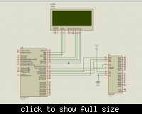
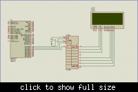
Thanks for everybody, but I solved my problem by making a "2 to 4 decoder".
So only 2 wires are needed for a single stepper motor. Only 14 I/O pins for 7 steppers.

I did ony the simmulations by Proteus.

Please visit >>> Electronics and Information Technology | free Electronic and IT books and make the comment for its pros and cons.
Thanks...!!
 

i want to drive 7 stepper motors, dual line 16 char lcd module and a single port for inputs.
I am using 16f877a .

How can i have that much of i/o pins by cascading or synchronizing or any other method using multiple 16f877a chips.
I am using mikroc for development.

4 wire spi -> 23s17 16 bit port expansion [3bit h/w addressable ]
3 wire lcd module [74hc595+lcd ]

- - - Updated - - -

I want to drive 7 stepper motors, dual line 16 char LCD module and a single port for Inputs.
I am using 16F877A .

How can I have that much of I/O pins by cascading or synchronizing or any other method using multiple 16F877A chips.
I am using MikroC for development.

4 WIRE SPI IO-EXPANDER MCP23S17 ->16 BIT OUTPUT [3 BIT H/W ADDRESSABLE ]
3 WIRE LCD -> 74HC595+LCD MODULE


Status
Not open for further replies.

Similar threads

Part and Inventory Search

Welcome to EDABoard.com

Sponsor

Back
Top