Continue to Site

Welcome to EDAboard.com

Welcome to our site! EDAboard.com is an international Electronics Discussion Forum focused on EDA software, circuits, schematics, books, theory, papers, asic, pld, 8051, DSP, Network, RF, Analog Design, PCB, Service Manuals... and a whole lot more! To participate you need to register. Registration is free. Click here to register now.

How to get Axial Ratio Along Frequency in CST MW?

Status
Not open for further replies.

Younker_899

Newbie level 6
Newbie level 6
Joined
Mar 3, 2012
Messages
14
Helped
0
Reputation
0
Reaction score
0
Trophy points
1,281
Activity points
1,364
Hello Friends

How i get Axial Ratio VS Frequency in CST MW in graph.
Please help me in that.

Thanks in advance

Regards
Junaid Iqbal
 

Dear Sir

Please if you explain this in more steps so i got the exact point.
Thank you

Regards
 

Hello
Sir i follow your step but i couldn't find the exact point(Axial Ratio VS Frequency).

Regards
Junaid Iqbal
 

Hello, Junaid Iqbal

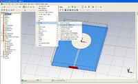
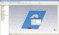
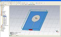
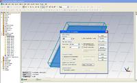
There is images, which represent the steps:

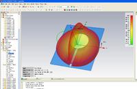
1.This step necessary to display of farfield for different frequencies

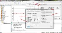
2. Frequency range and step size are set

3. Appropriate list is displayed in navigation tree

4. Start solver

5. There is result of farfield at frequency band


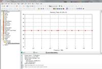
This results (graf of axial ratio) can be copied at different new folder.

Sir i am so thankful but i want to plot the AXIAL RATIO along with Frequency Plot.....So how can i plot them?

Regards
 

Hi, Younker_899.

Then, you should do the following:

1:
2:
3:

Hi Marat86,

thanks for your info.
after we get the axial ratio graph, how to check whether our antenna is circular or linear?
thanks
 
  • Like
Reactions: amntt

    amntt

    Points: 2
    Helpful Answer Positive Rating
Hi Marat86,

thanks for your info.
after we get the axial ratio graph, how to check whether our antenna is circular or linear?
thanks

After plot if Axial Ratio value is less than 3dB then your antenna is Circularly polarized and if greater than 3dB your antenna is linearly polarized

Regards
 

Hello,
i want to know, how boresight direction is defined for a cpw fed patch antenna, also in which direction do we usually measure x-pol and AR (e-plane max, h-plane max or boresight)
thanks
 

marata and yonker,
when we plot axial ratio in this way we are plotiing axial ratio along theta =90 and phi =0 but normally in hfss we plot it for theta=0 and phi=0 for checking axial ratio along boresight?so is it right to plot it in this way???? also can you plz show ur graph of ax v/s fre in cst so that i can get idea?/
After plot if Axial Ratio value is less than 3dB then your antenna is Circularly polarized and if greater than 3dB your antenna is linearly polarized

Regards
 

Status
Not open for further replies.

Part and Inventory Search

Welcome to EDABoard.com

Sponsor

Back
Top