hussien55
Newbie level 4

View attachment Nokia small one 5v,800ma.BMP
Hi dears,
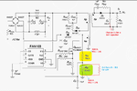
This is the circuit schematic simulation of NOKIA AC-15E charger. what i want "please advise me how could i get 12v instead of 5v with the same current".
Hi dears,
This is the circuit schematic simulation of NOKIA AC-15E charger. what i want "please advise me how could i get 12v instead of 5v with the same current".