Continue to Site

Welcome to EDAboard.com

Welcome to our site! EDAboard.com is an international Electronics Discussion Forum focused on EDA software, circuits, schematics, books, theory, papers, asic, pld, 8051, DSP, Network, RF, Analog Design, PCB, Service Manuals... and a whole lot more! To participate you need to register. Registration is free. Click here to register now.

how to "fix" my S22 and S33 for my power divider

Status
Not open for further replies.

vioamethyst

Member level 3
Member level 3
Joined
Nov 23, 2009
Messages
54
Helped
1
Reputation
2
Reaction score
1
Trophy points
1,288
Activity points
1,657
i currently in progress of designing lossless power divider, T-junction

i use equal power divider (with input feed 50ohm), connected to QWT*, and to the output feed which will later combine to antenna.

the feed is connected to QWT and directly attach to 50 output feed iwhich is bent (+ mitter bent)

when simulating my results, i obtain S11 which is well below -10dB, but unfortunately for my S22=S33= -8dB which is bad, if im nt mistaken, this happen due to significant loss.
what can i adjust to my design, so that i can obtain better value of s-parameter?

(without changing to other types of power divider eg wilkinson power divider, my power divider suppose to works on 3.5GHz)

*QWT= quarter wave transformer
here i attach along , some related files for your reference, thx in advance
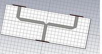
 

Attachments

  • my power divider.bmp
    1.3 MB · Views: 194

Microwave Engineering, David Pozar has useful discussion of various junctions. I have found his discussion useful in the past. I would start there to figure out what to fix. You might also want to check your miter to see if it was working as you expect. (Howe has guidance on miters).

---------- Post added at 19:05 ---------- Previous post was at 18:26 ----------

Howe, Stripline Circuit Design ..... pages 47-50.

By the way, I was surprised to find that swept bends are inferior to mitered bends until the radius of the sweep is significantly above the width of the line (~3 to 4 times as I recall). Howe is in stripline, but the trends in microstrip are similar. If you have space to burn (I know, there is never enough space) you might consider gentle swept bends.

I note that the layout of a t junction above has a v notch at the junction. I have seen t junctions made with and without this feature. The layout also does not show quarter wavelength matching sections.
 
  • Like
Reactions: kayaoo

    kayaoo

    Points: 2
    Helpful Answer Positive Rating
i have that pozar book
mine is pozar'z book , 3rd edition
that page of 47-50 is refering to which book? i hv check on the pozar's book for these page..but its seem unrelated, are u refering to other books?

im using microstrip line for my design,
yeap...about the swept bend..the curve bend right? i have discuss with my lecturer about bending in the past....she said..yeap that sort of bending need 3 times the width of line, which is space consuming (xpreferable)

mitter bend is better, in a way of space consuming which is better than that bend (correct me if im wrong)

at the junction from the between source feed to QWT have the V notch, erm, this is actually meant to reduce loss....if no sorts of bending there...there will be loss...

the layout u seen (which i attach earlier) is the layout which i take after "playing" with the width of 50ohm feed, thats maybe explaining why u see the width of 50 ohm feed is almost similar with width of QWT, while changing the width of 50 ohm output feed (to antenna) and input feed (from source), i
notice the terible perfomance of s22 and s3 is still there, i think the loss is due to the bending

practicallly , if u face these problem, may i know what u usually do?
im appreacuate ur reply, and thx a lot
 

Howe: 1974 Copyright; fourth printing, 1982

Pozar discuses various types of junctions and the expectations one might have for each, e.g. s11, s22, s33, s21, s31, s23, etc. As I recall it was in his Microwave Engineering book not the Antenna book. My recollection is that a simple t-junction cannot be well matched at all ports (so you may not be as far off as you think) but I would want to reread the section again. Please do not take this as gospel, rather find the applicable section and read it again. Post your conclusion so no one is lead astray. I did not go back to Pozar when I responded, that step I will leave to you.

By the way, in my experience, high loss often leads to excellent reflection coefficients. Not necessarily a good thing.
 

What are your QWT section's characteristic impedances?

If you can use 70.7 ohms, s22/s33 SHOULD be significantly better. This thing really shouldn't be made that complicated.
 

Azulykit: yeap..its cannot be well match, but i just hopin, at the very least the s22&s33 will equals to -10dB
will cntinue read pozar book @.@ anyway thx for the response
cnm: my QWT characteristic impedance is 70.71ohm, source impedance (input feed) = 50 ohm, output feed = 50 ohm too
initially between the input feed and QWT , there is 100 ohm line..but i remove that since it doesnt make much different, plus, i have read from some jurnal, that 100 ohm can just be ZERO length if we want to, cos nt affect anything =]
 

i have solved my problems,.....thanx to all....=]
 

Did you try something different from above? Let us know.
 

am teribly sory for the late reply to everyone
i notice using lossless divider giving me high loss , plus with the use of parallel feed network (in my case) con tribute to significant mutual coupling between elemnt in my array

so now, im trying my luck with series feed network, tho its less degree of freedom from the parallel network, it does solve my problem in mutual coupling.
thanx
 

Status
Not open for further replies.

Part and Inventory Search

Welcome to EDABoard.com

Sponsor

Back
Top