Continue to Site

Welcome to EDAboard.com

Welcome to our site! EDAboard.com is an international Electronics Discussion Forum focused on EDA software, circuits, schematics, books, theory, papers, asic, pld, 8051, DSP, Network, RF, Analog Design, PCB, Service Manuals... and a whole lot more! To participate you need to register. Registration is free. Click here to register now.

How to extend simulation time in Orcad Pspice?

Status
Not open for further replies.

gatedriver

Junior Member level 1
Joined
Jul 4, 2011
Messages
17
Helped
0
Reputation
0
Reaction score
0
Trophy points
1,281
Activity points
1,455
Dear all,

How can I extend simulation time in Pspice?

I am doing DC/AC converter with real gate driver.

I also read many convergence problem but I can not solve.

my system has RC circuit time constant: Tau=0.235us
switching frequency: f=5kHz ==> T =0.2ms
output frequency f=60Hz

When I choosed TSTOP = 0.7ms --> It's okie

But I need see the output voltage f=60Hz (T=16.67ms), so when I choose TSTOP =16.67ms --> the convergence problem appear at about 0.42ms, when the swiching device transfer.

I already choose RELTOL = 0.01; VNTOL = 0.01; ABSTOL 0.01u ; CHGTOL = 0.01u; ITL4=40;

Please give me some helps.

Thanks you very much
 

What maximum timestep have you set? If you are using the defaults, try setting a small minimum timestep, maybe 10ns.

Keith
 

Dear Mr. Keith

Thanks you for your reply

I've tried with maximum step 10ns but not success. convergence problem appear at 0.22us

How can i set up minimum time step in Orcad Pspice 16.2?

I think the convergence problem may be related to the time step !?

I already applied RC snubber circuit for diode and IGBT but the convergence problem error detail usually relate to switching device.

How can i do?
 

try using "autoconvergance" feature. You can turn on the autoconvergance from Option tab in simsetup.

Try to look for transition in your circuit at 0.42mSec and if you can do something changes in circuit to prevent abrupt transition.
You can also try the following

Check the run in resume mode in Simsetup>Analysis TAB
Choose run to time as 0.7msec
RUn the simulation
Now PSpice will complete the simulation and pause at 0.7msec (instead of finish)
Now change the value to somewhat higher value instead of 0.7m in runfor edit box

hit the run button (green color)
See if this let you complete the simulation
 
Dear all,

When I ran my circuit, from the beginning the error occur like this:
Disk write error. The disk may be full.
ERROR -- Disk write error. The disk may be full.
Run aborted
Simulation aborted

From some hints, I already modified Pspice initial file : PSpice.ini by adding MathExceptions=off into this file.


And the result is my circuit can run in long simulation time (TSTOP=20ms)

But I can not see the results in the Schematic ("There is no valid data points for trace 0 plot 0)


Please give me some hints

Thanks
 

A bigger disk?

You should be able to limit the data saved. You could not include subcircuit nodes, for example. Another option should be to output the data at the "print step" interval rather than at every time step. I don't use Pspice but you should be able to find the options in the help files.

Keith
 

Dear all,

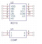
In the Pspice model of IR2113, there are IR2113 blocka and COMP block like this COMP.JPG

.SUBCKT COMP 1 2 3 4
E1 5 4 VALUE={IF((V(1)>V(2)), V(4)+5V, V(4))}
R1 5 3 1
C1 3 4 10P
.ENDS

I think it relate to Vs and Vss offset voltage but I do not know how to use it? (how to connect it with IR2113 pins)

I try do simulation about bootstrap circuit, so the Vs undershoot is so important.

Could you please show me how to use COMP block?

Thanks a lot!
 

Attachments

  • COMP.JPG
    COMP.JPG
    6.1 KB · Views: 134

You don't use the COMP subcircuit. It is internally used by the IR2113 model in lines such as

X_MD1_Trig3_Comp LIN MD1_Trig3_3 MD2_Inv2_1 com COMP


Keith.
 
Dear

I do step by step to check every components in my circuit, and now I want to test IR2113

I already read datasheet about it, and refered design tips and other posts in this forum. And I connect IR2113 like following figure for checking its operation

IR2113.JPG

But the error
INTERNAL ERROR -- Overflow in device X_U1.E_MD3_DlyHS_ABM24, Convert

and in Pspice model this device is defined:
E_MD3_DlyHS_ABM24 MD3_DlyHS_3 com VALUE { (EXP(-({tonVdd1}+({tonVdd3}-
+ {tonVdd1})/({V3}-{V1})*(V(VDD)-{V1}))/10/10n))/((EXP(-({tonVdd1}+({tonVdd3}-
+ {tonVdd1})/({V3}-{V1})*({V2}- {V1}))/10/10n)))
+ *(5* EXP(-( {tonT1}+({tonT3}-{tonT1})/({T3}-{T1})*(TEMP-{T1})) /10/
+ 10n))/(5* EXP(-( {tonT1}+({tonT3}-{tonT1})/({T3}-{T1})*({T2}-{T1})) /10/
+ 10n))*5*EXP(-{tonT2}/10/10n)* (EXP(-({tonV1}+({tonV3}-{tonV1})/({V3}-
+ {V1})*(V(MD3_DlyHS_1)-{V1}))/10/10n))/((EXP(-( {tonV1}+({tonV3}-{tonV1})/({V3}-
+ {V1})*({V2}-{V1}))/10/10n))) }

Could you please show me what are errors in my connection? How can I do to check and make sure this gate driver correct operation before I connect with power circuit?

Thanks a lot!
 

It is possibly caused by forcing a voltage in to the VB pin. That is an internally generated voltage. Have a look at the "typical connection" on the first page of the data sheet and follow that. You need to include a diode from Vcc to VB and a capacitor from VB and VS but don't connect VB to +15V - it could be at 500V!

Keith.
 
Dear Keith.

Thank you for your help

I draw my circuit refered "Typical connection" in datasheet

IR2113-2.JPG

But this time the error like this

X_U1._MD3_DlyLS_N2
RON 1
ROFF 1.000000E+06
VON 4.9
VOFF .1


INTERNAL ERROR -- Overflow, Convert
Disk write error. The disk may be full.
ERROR -- Disk write error. The disk may be full.
Run aborted


I known that I have to keep patience but some times I felt so confused!
 

If the disk really is full I cannot help you with that!

I wouldn't put capacitors directly across voltage sources with no series resistance. In fact if you use a perfect voltage source they won't do anything anyway. What they can do is cause infinite current which can cause problems. So, I would suggest you remove C3 & C2 unless they are subcircuits with series resistance. I don't know if it will solve your problem. One thing worthwhile checking is that your disk isn't full of data from old simulation runs. I don't use Pspice but I have my simulator set to delete all old simulation data files when you load the program.

Keith.
 

When the timestep downranges it will fill the disk with useless solution points.
You have to look for either a ridiculously small capacitance (which you might
cover up with cmin, if that's an available handle) ir a model singularity. Many
power FET models are kind of crappy, full of controlled sources and such
that can easily become unrealistic especially if you have high, fast transients.
Does your simulator allow you to set clamping limits (one I used to use, our
CAD guys had hacked VLIMAX and ILIMAX into to ensure that a runaway
transfer function could not explode).

Probe around just before the point of timestep downranging and look for
any crazy voltages / currents. If you know exactly the point, stop the
simulation just before it and dump the transient operating points for
review, looking for the crazy. It's tedious but maybe your only way to
pin down the offender.
 

Status
Not open for further replies.

Similar threads

Part and Inventory Search

Welcome to EDABoard.com

Sponsor

Back
Top