anotherbrick
Full Member level 4

- Joined
- Jan 10, 2009
- Messages
- 222
- Helped
- 1
- Reputation
- 2
- Reaction score
- 1
- Trophy points
- 1,298
- Location
- Istanbul , Turkey
- Activity points
- 3,190
hello dear forum

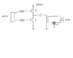
I try to measure output current of 28 KHz half bridge inverter with current transformer
the 1. opamp amplify current transformer output 2. opamp pass only positive alternance
the opamps are single supply the 7805 as voltage divider for amplifying negative signal by 1. opamp - I have put 10 uF 100 nF baypass caps to output of 7805 - no help
the opamps in the real circuit are AD8065 fast opamps
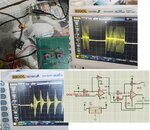
my problem ; if I connect current trasformer to the opamp circuit there is oscillation on top of current signal of CT - more interesting the oscillation is there only when the high MOS of inverter is ON
if I dont connect CT to opamp circuit there is no oscillation
also I have put damping resistor and 1 nF cap paralel to CT output - no help
my question how can I eliminate this oscillation ?
thank you


