Continue to Site

Welcome to EDAboard.com

Welcome to our site! EDAboard.com is an international Electronics Discussion Forum focused on EDA software, circuits, schematics, books, theory, papers, asic, pld, 8051, DSP, Network, RF, Analog Design, PCB, Service Manuals... and a whole lot more! To participate you need to register. Registration is free. Click here to register now.

[51] How to detect signal going low for 100usecs

Status
Not open for further replies.

hithesh123

Full Member level 6
Full Member level 6
Joined
Nov 21, 2009
Messages
324
Helped
1
Reputation
2
Reaction score
1
Trophy points
1,298
Location
lax
Activity points
3,548
How do I detect if a signal is low for a particular period of time say 100usecs.
The signal is usually a pulse with time period of say 50usecs.
I can't poll or keep waiting. It has to be interrupt based.
 

It would help if you could provide some details of your system
(software and hardware)
There are lots of ways you could do it.
 

It would help if you could provide some details of your system
(software and hardware)
There are lots of ways you could do it.

I am using C8051F120 with Keil C51.
 

Many ways to do it. A timer in capture mode is probably the best way to measure pulse widths.
 

Many ways to do it. A timer in capture mode is probably the best way to measure pulse widths.

It's not pulse width exactly.
The input goes low for at least 100usecs. After this, it may stay low.
I just want to detect if the input has been low for 100usecs.
 

Is there a way I can run Timer in only DOWN mode based on external pin status.
If Port is LOW, timer counts Down. Else if the port is high, Timer just stops.

I can only use ISR.
 

The posts refer to 50 and 100 micro second so it is getting lengthy. If it is matter of initiating an event when the pulse goes low, you can tie it to external hardware interrupt pin and the ISR code will do the needful. If the pulse duration is relevant, preprocessing of pulse may do it the application is not pulse width critical.
 

I'm not familiar with either the hardware or software you are using but a quick scan of the processor datasheet
reveals you have what you need -
There is a reloadable 16 bit counter/timer(Mode 2: 8-bit Counter/Timer with Auto-Reload) so you can count up to anything
you like (it flags the overflow - just add your own counter when the flag is set to extend the time)
All you need then is an I/O pin with interrupt on change - take a look at (Edge-triggered Capture Mode p329)

It should be easy enough.
 

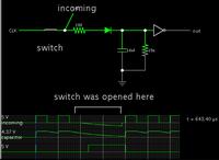
Connect a RC circuit to INTx pin. I guess your pulses' high value is 5V. The capacitor should charge to 5V. The T (tau) should be such that capacitor doesn't discharges to a voltage equal to low value required for INTx to detect high to low transition for your pulse off time. INTx should be configured to detect high to low transition. Now if there is no pulse for 100 us then capacitor should discharge to a value which will be low for INTx pin.
 

Simulation of the method described in post #10.

It is similar to what the 555 IC does when set up as a missing pulse detector.

The output goes high only when the capacitor is not replenished by an incoming pulse.


there is no reason to use external circuitry. Everything is available on chip - as I said in 9.
 

there is no reason to use external circuitry. Everything is available on chip - as I said in 9.
Yes, see also post #4. A developer who's unable to cope with timer and interrupt programming might prefer a straightforward hardware solution though.
 

my message in #9 provides the response requested in #6 and indeed does reflect your message in #4
I dont think providing extra circuit complication is a good way to go even for novices though.
 
  • Like
Reactions: FvM

    FvM

    Points: 2
    Helpful Answer Positive Rating
Status
Not open for further replies.

Part and Inventory Search

Welcome to EDABoard.com

Sponsor

Back
Top