Continue to Site

Welcome to EDAboard.com

Welcome to our site! EDAboard.com is an international Electronics Discussion Forum focused on EDA software, circuits, schematics, books, theory, papers, asic, pld, 8051, DSP, Network, RF, Analog Design, PCB, Service Manuals... and a whole lot more! To participate you need to register. Registration is free. Click here to register now.

[SOLVED] How to decrease the buzz noise of the circuit board?

Status
Not open for further replies.

tony_lth

Advanced Member level 5
Joined
Jul 28, 2010
Messages
2,098
Helped
377
Reputation
756
Reaction score
369
Trophy points
1,363
Location
Beijing
Activity points
12,727
When the board works in GSM mode, we can hear the buzz noise of the board. But in other mode, there is no buzz.
The most important noise is 5th harmonics of 217Hz (that is generated by GSM system).
How to solve that or decrease the noise?
Conditions:
1. There is one buck circuit, so maybe caused by the buck inductor. If so, how to detect it and how to solve it?
2. There are about 20 MLCC capacitances, those are 22uF and in 0603 or 0805 package. How to detect which one cap buzz and how to solve the buzz or decrase the buzz?
3. Any other root causes?
Thanks for your reply.
 

a microphonic buzz? , you mean like the EMI ingress sound on speakers and microphones that happens every few minutes to re-Tx and verify best tower connection?

Self ingress on SMPS is hard to track. Finding the mechanism of ingress from A to B is the key, then the solution is easy. It is not clear what is point B in your case.
YOu need to try different methods to make better or worse by experiment. ferrite coupling, shielding, conducted CM line filtering with low permeability. Clarify exact noise interference. All ceramics and ferrite are microphonic, but ferrite is RF absorptive. That should be your clue. But it could be conductive noise interference with 2 SMPS in series. Add very low ESR caps.
 
In GSM, the 217Hz is a sensitive issue and happened due to the 4.6 msec TDMA operation of the RF power amplifier.
The most important thing to avoid this problem is the layout design of the audio circuits of the mobile, mainly following the old rules of the audio amplifiers PCB design (a lot of designers don't follow, or do not understand this basic rules).
Using full differential lines connecting the audio circuits it will help a lot fixing 217Hz issue, providing good CMMR and rejecting possible noise.
Need to use an audio amplifier with a stable distribution of PSSR (Power Supply Rejection Ratio) in 100Hz to 1kHz frequency range.
If appears, there is not an easy fix for this problem, and sometimes in top of your knowledge's you need to get some luck.
 
Hi, SunnySkyGuy, the board has buzz noise even without earpiece, without speakers or microphones.
If put the board nearby the ear, people can hear the buzz noise.
So I will try later according to your suggest.
Thanks SunnySkyGuy and vfone.
Does Anyone have other suggestions?
 

The nature of the buzz is important. I once designed a video board for a wireless video head-mounted display with 2 SMPS. THe 9V batt had a buck 5V converter driving a 12V boost converter and the results was technically called CHAOS but it sounded alike running water or random noise. The source of noise was the epoxy filled secondary regulator choke and the solution was a low ESR cap in the right place. The technical reason for the white noise is well written in recent IEEE journals. But I heard it 10 yrs ago after a few minutes, said, wow I have realized true Chaos controlled SMPS that sounds like a babbling water stream. Remember piezo electric effect in ceramics and spurious sub-harmonics common to certain SMPS modes of regulation are prone to this. The frequency at minimum phase margin or loop bandwidth at 0 phase margin can also cause oscilations. YOu might also have an intermod product with beat frequency of two constant F regulators.

Or it may simply be the transmitter resonating a speaker in the near field of the antenna every few minutes during cell tower re-sync.

YOu never described the details of the buzz.. with power on/off... on-hook, interval, steady... 60Hz buzz? etc !!

leaving me to do a lot of guessing....
 
Tony,

>> If put the board nearby the ear, people can hear the buzz noise.
That sounds like an inductor to me. Using a screwdriver (with a plastic handle), put the handle against your ear and probe around with the screwdriver. It will be loudest around the offending inductor. I haven't herd this problem since the tube days.
 
Hi, SunnySkyguy,
Next week I will try to find one board and decribe the noise. It is not obvious and normally is masked by environment noise. But if put the board nearby your ear, you can hear it clearly. The noise is steady noise.
Hi, ge,
Good idea. I will try.
Thanks you all.

- - - Updated - - -

Hi, ge,
Could you please provide a solution if it is caused by the inductor?
How to solve it?
 

one would need an description of the circuit, schematic or at least a photo.& audio recording

If I had my crystal ball, it might resonate.

1) isolate source
2) determine cause
3) then fix it (should be obvious.)

trying in reverse order is a bit illogical
 
Last edited:
Thanks, SunnySkyguy, because PCB and SCH are confidential, but I can post the audio test result later.
Thanks for your quick reply.
 

trying to localize the source of the sound as suggested above can work. Usually putting stress on the offending component will change the sound, so just push each capacitor/inductor with a plastic screwdriver or something and see if it has an effect. For capacitors, make sure you use high quality dielectric, and for inductors it's somewhat random whether they make sound or not. It's just a matter of finding one that is rigid at your problem frequency.
 
mtwieg makes a good suggestion for finding the offender (putting stress on the offending component will change the sound). It changes the stress on the windings.

I've never seen this on a switching regulator but in the olden days, we would refer to this as a weak power transformers . The windings were typically damaged by heat. It still sounds like an inductor to me.
 
The chaos sound I had was a PFM modulated 150KHZ~200KHz boost regulator with SMD epoxy resin inductor being the speaker loading a PWM step down regulator @100KHz ......causing pseudo random noise in 500~5KHz range, THis is "Chaos" and the FM modulated noise was in the audio range sounded like running water. Chaos Theory supported this instability. Changing loop filter to decouple the 2nd SMPS with lower ESR cap stopped the spurious noise... but your situation is different.
 
wow I have realized true Chaos controlled SMPS that sounds like a babbling water stream

This also happens to be how the economy behaves, among other things ... just instilling extra confidence. =)
 

Another way to localize noise of this type is to use a short piece of flexible hose. Hold one end to your ear and move the other end around just above the board. When you come near the noisy component you'll hear it through the hose. This may be better than the screwdriver because it doesn't involve touching the board at all.

Ed
 
If inductor, you can also alter frequency or amplitude with a magnet touching component. Better chokes are torroids with epoxy vacuum-processed coating. Adding ESR to reduce current helps reduce magnet forces on windings with efficiency trade-off.
If ceramic (MLC) device resonating, use plastic cap with lower ESR ( eg polyurethane Panasonic).
If SMPS resonating from instability, then scope signals and show pictures. These are not proprietary since it is anon.

Yes the stock market is said to follow pseudo random noise with bias from inside trading. (a.k.a. Chaos Theory )
 
Another way to localize noise of this type is to use a short piece of flexible hose. Hold one end to your ear and move the other end around just above the board. ......
We even used Stethoscope without the head to hear the noise. But it doesn't work. Because the board is very small, the total size is about 30mmX30mm. And the board is about 10 layers. The board has more than 20 capacitances, which is 22uF MLCC with 0603 packages, etc. The board has one inductor and about 10 ferrite beads. And surely it is very hot during working.

- - - Updated - - -

The noise is almost same everywhere when used Stethoscope, but I will try screwdriver later.
 

That is a small board especially with 0603 caps plus inductors and such. I doubt the screwdriver trick will work if you tried a stethoscope. I'm guessing you tried pushing down on components while the noise is being made using a plastic or wooden stick. It still sounds like inductor windings and the ferrite resonating. Is there any chance you are massively saturating the core?

- - - Updated - - -

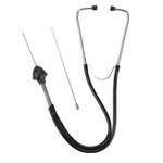
Possibly my misunderstanding. Was that a medical or automotive stethoscope? Pic of automotive stethoscope attached.
 

Attachments

  • stethoscope.jpg
    stethoscope.jpg
    7.9 KB · Views: 182
Hi, ge,
I used medical stethoscope. Can automotive stethoscope work here?
Thanks.
 

It seems the copper ground plane is radiating the sound everywhere.

Can you not effect a change in level by using your finger to dampen the vibration or correlate the frequency with any signal on board?

Where is the audio sample? Use a stick mic for radiated near field sound and then touch for conducted vibrations.
The hottest passive parts should be suspect 1st. watch out for high power RF on eyes. it causes blood shot effects.

Add ceramic caps in parallel on top if necessary. but if they are not low enough ESR at operating RF frequency, you need to change caps to make sure SRF is > operating current F and consider polyurethane caps from panasonic for DC.
 
Last edited:
The automotive stethoscope is the "correct" tool as compared to a plastic handled screwdriver, but no one ever accused me of using the correct tool for the job.

>> you tried pushing down on components while the noise is being made using a plastic or wooden stick?
Did it change the noise (amplitude or pitch)? Fingers also work if the part is large enough and you are not afraid of burns or throwing an amplifier into oscillation.

Can you tell us what type of inductor you are using Coilcraft, Toko, Piconics, Bobbin, Button, Toroid, etc. Can poke a Q-Tip or coffee stir straw stick directly on the windings?

SunnySkyguy is correct in that the hottest "passive" part should be suspect first.
 
Status
Not open for further replies.

Part and Inventory Search

Welcome to EDABoard.com

Sponsor

Back
Top