TerryADS
Full Member level 2

Dear friends,
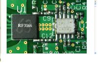
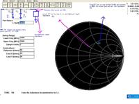
I have a PA demo board.vendor supply us the MMIC PA load pull impedance and PCB.and duplex follow PA.my work is debug the board.some documents tell me:firstly connect the componts in series with 0R between PA and duplex,measure the output impedance,then match the load pull impedance to measured one.
Normally,when designing match,we use capacitor,micrstrip or inductor matching step by step.But debugging seems another thing(connect the componts in series with 0R,measure the output impedance,then match the load pull impedance to measured one.),why not we measure the impedance before duplex,get the impedance,and make match,but using the above process?
Thanks,


