Continue to Site

Welcome to EDAboard.com

Welcome to our site! EDAboard.com is an international Electronics Discussion Forum focused on EDA software, circuits, schematics, books, theory, papers, asic, pld, 8051, DSP, Network, RF, Analog Design, PCB, Service Manuals... and a whole lot more! To participate you need to register. Registration is free. Click here to register now.

How to Create 1-bit ADC?

Status
Not open for further replies.

sisso

Newbie level 4
Newbie level 4
Joined
Jun 6, 2011
Messages
6
Helped
0
Reputation
0
Reaction score
0
Trophy points
1,281
Activity points
1,329
Someone tell me circuit diagram of a 1-bit Analog to Digital converter with chip no.'s mentioned. All the things resistors,capacitors with proper values mentioned.

I want to create a device that reads 5V DC signal and convert it into binary signal. Then this binary signal is transferred to USB port of a PC and an application reads it.
 

A simple comparator circuit is most basic example of 1 bit ADC.
 

A simple TTL input also performs that feature.

+++
 
  • Like
Reactions: sisso

    sisso

    Points: 2
    Helpful Answer Positive Rating
A 1 bit ADC is just a comparator. You could use a whole wide range of ICs to achieve this, right from LM741 to LM311. Depends on the situation and supply voltages availabe.
 

A 1 bit ADC is just a comparator.
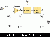
Yes, if the term is read literally. "1-Bit ADC" is however usually referring to an oversampled (sigma-delta) ADC structure. Besides a comparator, it involves a feedback modulator, that converts the analog input signal to a binary data stream of same average value. To make the circuit shown by KerimF work as a 1st order SD modulator, you would want to connect Rx to the FF output rather than to it's input.

The original question doesn't clarify, why a "1-bit ADC" should be used. It effectively asks for a ADC to convert a 5V input signal, without specifying a resolution. We can e.g. use an USB microcontroller with a built-in ADC and connect it to the USB.
 

yeah true, using FPGA even a 24 bit DAC can be synthesized using a 1 bit sigma delta modulator.

refer to this paper if interested:
An FPGA Implemented 24-bit Audio DAC with 1-bit Sigma-Delta Modulator by Xiaoxiao Li and Alex Lee

Didn't want to divert the topic with sigma delta modulators.

@sisso, please tell us where you'll be using this, so that we can post a circuit which satisfies your requirement.

I have a device that supplies 5 V signal each time a object passes through it, I want to detect this 5V signal through USB port of a PC (that is not possible directly) and an application increments a variable each time it receives this signal. Aim is to built a counter. This is needed because later LPT port was available on systems on which pin 17 directly receives 5V signal and an application receives it. This is not possible with USB port. Thats why I need an ADC to convert this 5V to binary and this binary could be readed by USB port.
 

So you are basically looking for a single digital input, not an ADC or comparator. To connect a digital signal to usb, you need an USB device with respective input(s).

Have a look at the Data Acquisition links at Jan Axelson's USB Central **broken link removed**

Also an FTDIchip USB interface, e.g. FT232R or FT2232 cab be used as didgital input.

Most digital USB interfaces can accept a 5V digital signal without additional level conversion.
 

Status
Not open for further replies.

Similar threads

Part and Inventory Search

Welcome to EDABoard.com

Sponsor

Back
Top