Continue to Site

Welcome to EDAboard.com

Welcome to our site! EDAboard.com is an international Electronics Discussion Forum focused on EDA software, circuits, schematics, books, theory, papers, asic, pld, 8051, DSP, Network, RF, Analog Design, PCB, Service Manuals... and a whole lot more! To participate you need to register. Registration is free. Click here to register now.

how to convert a sine wave with 100mV Vpp to square wave with rail to rail?

Status
Not open for further replies.

turtlewang

Member level 2
Member level 2
Joined
Nov 7, 2010
Messages
46
Helped
1
Reputation
2
Reaction score
1
Trophy points
1,288
Activity points
1,605
Hello everybody,

I want to convert a sine wave clock signal to a square wave clock. The sine wave is a clock signal generated from off-chip signal generator. It is frequency is 2.5GHz, it's peak to peak value is 100mV. I want to design a circuit to convert this clock signal to a square wave with rail to rail. Then I will use this square wave to clock my CMOS circuit.

My process node is TSMC 0.18um.

Does anybody know what is the common architecture for this purpose?

Can anybody recommend me some materials?

Thanks in advance!
 

Use a comparator to convert the sine wave to square wave. You can fix the threshold based on the duty cycle that you want. Fix the swing of the comparator based on the peak to peak signal that you want.
 
Thanks Srinivasan, Is there some other way to do this job? Because I find some commercial chip doesn't use comparator .
Use a comparator to convert the sine wave to square wave. You can fix the threshold based on the duty cycle that you want. Fix the swing of the comparator based on the peak to peak signal that you want.


---------- Post added at 08:58 ---------- Previous post was at 08:42 ----------

Some circuit which generates the threshold voltage is needed if I use comparator to do this job. Because the input clock is differential, I want to use some sort of amplifier to do this job. But now, I have no ideas about how to do it.

Thanks Srinivasan, Is there some other way to do this job? Because I find some commercial chip doesn't use comparator .
 

Feeding a 2.5 GHz square wave with CMOS IO standard isn't a serious option. You have to generate it on chip. The term square wave is questionable for a 2.5 GHz clock anyway. You'll rather expect a kind of rounded trapezoid. For various reasons, you would want to use low voltage differential signaling for the clock. Expecting a 2.5 GHz full voltage swing for a clock input sounds like a complete design dead end.
 

Since the clock is so fast, it is hard to run it on PCB level. PCB parasite is so big.
 

Yes, I just want to generate the 2.5GHz square wave on chip. The generation is based on sine wave which is fed off-chip. The sine wave is low swing signal which peak to peak value is 100mV.
Feeding a 2.5 GHz square wave with CMOS IO standard isn't a serious option. You have to generate it on chip. The term square wave is questionable for a 2.5 GHz clock anyway. You'll rather expect a kind of rounded trapezoid. For various reasons, you would want to use low voltage differential signaling for the clock. Expecting a 2.5 GHz full voltage swing for a clock input sounds like a complete design dead end.
 

Either differential amplifier (for differential clock signal) or self biased inverter (for single ended). Additional inverters to increase the level.
 

The amplitude (peak to peak 100mV) is so small. Self biased inverter might not be OK.
 
  • Like
Reactions: FvM

    FvM

    Points: 2
    Helpful Answer Positive Rating
Self biased inverter might not be OK.
It's no problem of the inverter circuit as such, i think. But practically, ground bounce seriously interfers with the small voltage. For this reason, a differential amplifier is clearly preferable.

I assume, that the solution can be found in most IC design text books.
 
So How about a differential amplifier followed by a self-biased inverter?

Can you give me an example of the text book?

Thanks very much!

It's no problem of the inverter circuit as such, i think. But practically, ground bounce seriously interfers with the small voltage. For this reason, a differential amplifier is clearly preferable.

I assume, that the solution can be found in most IC design text books.
 

A self biased inverter needs a coupling capacitor on input, so it won't be available on chip.

Differential input stages for low level differential GHz signals are commonly used for IO standards like SATA, PCIe, USB3. Similar input stages can be used for low level single ended AC signals as well (with a RC low pass feeding the negative input) and should work for your design, too.
 
Thank you very much!

Can you recommend me some materials about this input stages?

Or can you give me some key words that i can google it or find some papers in IEEE database?

Since I want to know both the architectural aspect and transistor level of the input stages. For example, how many amplification stages are suitable for this job, and what are the advantages and disadvantages of different implementations?


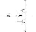
Another question is : why does self inverter need a coupling capacitor? I don't know the schematic of self biased inverter, but I guess it is like this:
Untitled.jpg

A self biased inverter needs a coupling capacitor on input, so it won't be available on chip.

Differential input stages for low level differential GHz signals are commonly used for IO standards like SATA, PCIe, USB3. Similar input stages can be used for low level single ended AC signals as well (with a RC low pass feeding the negative input) and should work for your design, too.
 
Last edited:

Thanks Srinivasan, Is there some other way to do this job? Because I find some commercial chip doesn't use comparator .


---------- Post added at 08:58 ---------- Previous post was at 08:42 ----------

Some circuit which generates the threshold voltage is needed if I use comparator to do this job. Because the input clock is differential, I want to use some sort of amplifier to do this job. But now, I have no ideas about how to do it.

If your chip input clock is a sinusoidal differential signal with 100mV amplitude all you need to look up is an LVDS receiver (designed to work with square waves with 350mV differential swing and a common mode of 1.25V+/-1V) and tweak it to manage 100mV swing (basically make sure the input diff amp offset is low enough and that your signal common mode fall in the LVDS range)

Since you are using sinusoidal instead of square wave input make sure your LVDS reveicer has some hysteresis, the positive feedback will take care of make the sharp transitions

Given your speed requirement a cascade of latched comparators should do the job
 
thanks dgnani, I will try it!
If your chip input clock is a sinusoidal differential signal with 100mV amplitude all you need to look up is an LVDS receiver (designed to work with square waves with 350mV differential swing and a common mode of 1.25V+/-1V) and tweak it to manage 100mV swing (basically make sure the input diff amp offset is low enough and that your signal common mode fall in the LVDS range)

Since you are using sinusoidal instead of square wave input make sure your LVDS reveicer has some hysteresis, the positive feedback will take care of make the sharp transitions

Given your speed requirement a cascade of latched comparators should do the job
 

Status
Not open for further replies.

Part and Inventory Search

Welcome to EDABoard.com

Sponsor

Back
Top