Continue to Site

Welcome to EDAboard.com

Welcome to our site! EDAboard.com is an international Electronics Discussion Forum focused on EDA software, circuits, schematics, books, theory, papers, asic, pld, 8051, DSP, Network, RF, Analog Design, PCB, Service Manuals... and a whole lot more! To participate you need to register. Registration is free. Click here to register now.

How to control Voltage and Current

Status
Not open for further replies.

plmrguest

Newbie level 3
Newbie level 3
Joined
Nov 20, 2015
Messages
3
Helped
0
Reputation
0
Reaction score
0
Trophy points
1
Activity points
25
I am trying to control voltage range from 1.5 to 34 using LM338 voltage regulator with 1000u capacitor at the input 430u capacitor at the output with potentiometer @ the adjustment terminal.

I have 37v and around 5 Amps current at the Vout but when i try to reduce the voltage using potentiometer,resistor 120 ohms burns out. Please suggest me how to control and get constant Voltage & Current.
 

you've not given us a lot to go on you need to show us how your diagram how you have wired it up, is there any load connected ??
What size and where is your 120R resistor connected.
 
  • Like
Reactions: gnm109

    gnm109

    Points: 2
    Helpful Answer Positive Rating
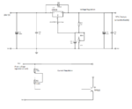
Here is my schematic for you reference i have both voltage and current , since we can't control both voltage & current
so i need to keep the voltage constant 32V and current should be adjustable.

power-supply.png

Here is my schematic for you reference i have both voltage and current , since we can't control both voltage & current so i need to keep the voltage constant 32V and current should be adjustable.

https://obrazki.elektroda.pl/4924388100_1448044162.png

Input is 26V and the output is 37 V what we are getting.
 

Hi,

It's good practice to tie the loose pin of the trimpot to the wiper, in the schematic those are RV1 and R3. If Bourns recommend it, I'll do as told!

I'm sorry, I don't understand your question very well. Do you mean you need 32V fixed output, and what current - adjustable or fixed?

Are you trying to do this:

338 typical application.JPG

If so, perhaps you have some components in the wrong place, or things like the second diode are missing (according to your schematic).

I haven't seen the circuit with a transistor after the output capacitor for current regulation before, that's new for me. I know the datasheet for the 138 (338) has a good number of schematics in "application hints" section, and page 14 has three different current regulating circuits to choose from.
 

How can the 37V output be higher than the 26V input??

- - - Updated - - -

Look at the datasheet. If you are using the TO-220 package then you have the pins of the LM338 connected backwards.
 

Just a thought, I discovered recently that the TIP125 very quickly gets alarmingly out of control where current is concerned with only 1mA base current..., it has a MINIMUM DC gain of 1000, so does the 122.............

Not sure the resistance you have going into the base of the TIP122, but perhaps the "uncontrollable" problem is related to this (inventing your circuit conditions, 30V/30Kohms = 1mA; if you have much greater resistance into the base e.g. 110K, then no idea of why that happens).

Disconnected from a circuit, I measured the resistance of the TIP125 and that of a 2N2222A from collector to emitter out of curiosity, and there is an alarming difference, my TIP125 had so little resistance in comparison to the other much lower gain BJT, which is not a Darlington, that when powered up it quickly reminded me of something about to become a short-circuit. The Darlingtons have been excluded from my transistor tester forever, unless I build a Darlington tester.

Maybe that's a good current regulating circuit you are copying, I don't know, but could be worth copying another with a diferent design - there are plenty in adjustable regulator datasheets, and unless you really need it, use a power BJT instead of the Darlington.
 

I will test your suggestion and reply you
 

Hi,

since we can't control both voltage & current
See both as maximum limitations.
You can set up a voltage limit to 5V for example, and set up current limit to 2A for example.
With a load resistance of 0...2.5 Ohms there will be the current limit active and the resulting voltage will be less than the limit of 5V
With a load resistance higher than 2.5 Ohms there will be the voltage limit active and the resulting current will be less than the limit of
2A.

There are ICs, where you are able to adjust both limits. Like the L200.

I personally don't like the huge power (heat) dissipation of linear regulators, therefore I the d to use switch mode voltage regulators.

To add a current limit you need a shunt to measure the current, a difference amplifier that amplifies the difference between current limit set point and actual current. The output with a series diode may be used to manipulate the feedback voltage in a way that the regulator lowers output voltage.

There will be lots of those circuits around I the internet, I'm sure in this forum also.

Klaus
 

Status
Not open for further replies.

Part and Inventory Search

Welcome to EDABoard.com

Sponsor

Back
Top