Continue to Site

Welcome to EDAboard.com

Welcome to our site! EDAboard.com is an international Electronics Discussion Forum focused on EDA software, circuits, schematics, books, theory, papers, asic, pld, 8051, DSP, Network, RF, Analog Design, PCB, Service Manuals... and a whole lot more! To participate you need to register. Registration is free. Click here to register now.

[SOLVED] How to control line voltage?

Status
Not open for further replies.

Kebabix

Newbie level 5
Newbie level 5
Joined
May 8, 2018
Messages
10
Helped
0
Reputation
0
Reaction score
0
Trophy points
1
Activity points
91
Hi there,

I'm trying to figure out how to successfully solve my problem.
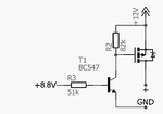
I have radio with constant 12V in it's connector and another 8.8V here, which appears only when I turn on the radio. Now, because I need this 12V, I would like to control line like this: when 8.8V is high, 12V appears; when 8.8V disappears, 12V isn't alive too. I had one solution suggested, but this circuit doesn't work properly:
**broken link removed**
When I connect constant 12V, it is here, in "+" pin. From my knowledge, 12V should appear when 8.8V is connected but unfortunately doesn't work like this here. Because I'm a newbie with such issues, I would like to ask you for some help. Maybe someone sees what is wrong here and know how to make it work right? Or maybe built another solution?

Best regards and thank you in advance for any help :)
 

Your attachment isn't valid. Please try again!
 

I'm sorry, something must have gone wrong.
Now I see image works, I hope.
 

Attachments

  • schemat.png
    schemat.png
    19.9 KB · Views: 169

Yes, now your image is visible. There are times when an attachment expires for no reason. It may help if members submit their post immediately after uploading an image.
 

Hi,

When I connect constant 12V, it is here, in "+" pin. From my knowledge, 12V should appear when 8.8V is connected but unfortunately doesn't work like this here.
This description doesn't tell about the 8.8V signal, so there is not enough information to verify the circuit.

The 8.8V signal goes to a bjt via resistor. Thus the ON/OFF threshold voltage is close to 0.55V.
I expect it to be OFF with input voltages <0.5V
And ON with input voltages >0.7V

The given schematic doesn't tell which Mosfet you use. Thus we can not verify if you used the correct type.

And even if the schematic is correct, there is the chance of an error in your connections.
If you want us to verify it, you should post a photo of your circuit.

Klaus
 
Kebabix.png

p-substrate of the n-MOSFET is connected to +12V - so you have a diode forward connection between +12V and your output - independent of gate control. Connect the substrate to its source (your output).
 
Guys,

firstly I would like to thank you for such response and willingness to help :)

MOSFET which I used is IRF9530, I forgot to include it in the schematic.

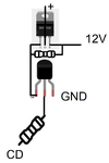
As KlausST suggested, I attach schematic with connection. Before doing what erikl proposed, I would like you to see this connection.

Best regards.
 

Schemat.png
Here's the schematic.
 

But it isn't a good news, unfortunately!

Do you have any idea where lies the problem, maybe?

Best regards :)
 

Hi,

The other end of R "CD" in the picture is a microcontroller 3.3V I/O pin?

Where's the BJT pulldown resistor? Try putting a resistor from NPN base to ground. (My) sloppy BJT switch circuit design revolves around the holy grail of 1k into base, 10k to ground/V+. It isn't science but it usually works.

Something else, in case it was an oversight:
Quick calculations: Ib = 8.8V/51k = 173uA
173uA * 10 = ~2mA Ic
Is 2mA enough to turn on the MOSFET per requirements or is the load light so the gate voltage level is more important than Ig level?

- - - Updated - - -

Hi,

As a simulation, it looks like the circuit from post#3 should operate correctly. It worked equally correctly for a 10k and a 1k load. Adding a base resistor to ground on the NPN won't hurt, anyway.

What is the load? Is it known or variable?

8V switch simulation.JPG
 

Hi d123,

thanks for your response.

I'll try to answer to your questions now:

-The other end of R's "CD" is connected with head unit pin which gives 8.8V when radio is powered on.
-I haven't tried adding resistor yet, but original schematic didn't contain such element. I see you simulated this circuit and it seems to work without resistor?
-When it comes to load terms: I would like to connect "+" pin to 5V stabilizer (LM7805) which gives me proper voltage usable with Arduino's VIN. I don't think Arduino and other stuff would take much mAs.

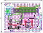
I decided to give you schematic of my whole project. I created CDChanger emulator working with my car's head unit, here's schematic (not mine):
liu_acp_aux_uno_protoshield.jpg
Now, you can see PWR and GND pins. I wanted to connect circuit from the topic here in order to control whole changer when radio is powered on.
Here comes schematic with similar changer, but created using ATmega8. It uses this dependence (CD pin) and turns on only when head unit is running.
iwnifmf.PNG
Again, it's not my work. I only want to use circuit controlling voltage in Arduino version.

Maybe you see something missing from my solution, but existing in above schematics?

Again, thank you for any help :)
 

Hi,

please do some mesurements and give us the vlaues:
(when CD = 8.8V = ON)
* measure the exact voltage "CD"
* measure the voltage B-E of the bjt
* measure the voltage C-E of the BJT
* measure the voltage Gate-GND of the MOSFET
* measure the voltage Source-GND of the MOSFET
* measure the voltage Drain-GND of the MOSFET

Klaus
 

Ok, guys, I have some interesting news!

Something poked me after reading @KlausST post: I realized that every previous tests were made on my desk, without actual use of head unit. I always connected power supply to 12+ and GND pins when checking it. So, I today I went to my car and connected my assembly - I couldn't believe what is happening. Circuit worked flawlessly, Arduino always turns off with head unit.

Previously, I went from assumption that I only need 12V in order to test it. You know, gate for me should be closed when 8.8V is absent here, so instead of trying it with radio, I checked it in home. Now it seems that CD pin is necessary for this solution to work. With radio switched off, I have voltage decreasing to zero on pins + and GND.

For you it may look like obvious discovery, but for me this experience is like pretty big lesson.

May I ask you why this circuit doesn't work properly without CD pin connected? Is it because R3 isn't connected to T1 so the gate can't work?

Best regards :)
 

Hi,
May I ask you why this circuit doesn't work properly without CD pin connected? Is it because R3 isn't connected to T1 so the gate can't work?

Do the requested mesaurements, and I can tell you.(Most probably you will see it on your own)
Measured voltages say more than all the words of post#14 ... at least I didn't understand them.

Klaus
 

Hi,

I have the measurments done:

-CD: 8,51V
-B-E: 0,651V
-C-E: 0,014V
-G-GND: 0,013V
-S-GND: 11,65V
-D-GND: 11,65V

I checked them in my garage so that's the reason why 12V values are lower.

Ps. I'm sorry for problem with correct understanding me. English language isn't my native language so, for me, describing everything in technical language is like some kind of challenge. I hope that given values will tell you everything.

Best regards :)
 

Hi,

-CD: 8,51V
-B-E: 0,651V
-C-E: 0,014V
-G-GND: 0,013V
-S-GND: 11,65V
-D-GND: 11,65V
This is correct function.

--> Please show the measurement when function is wrong.

Klaus
 

Hi, KlausST!

Sorry for long response time, I have finals incoming.

Function seems to be ok now, so I can't measure when it's wrong.
I wrongly connected assembly previously. I didn't know that this gate can't work properly, when 8.8V isn't connected - during tests I always had 12V only supplied, without CD pin.
Do you understand what I mean?

Best regards :)
 

Hi,

Do you understand what I mean?

Yes, I know what you mean.
Thus - if you read my first post - I told you that there is not enough information about the 8.8V signal.
I requested measurements .....

Klaus

PS:
Remember: don´t let signals floating. A floating signal is "undefined". This is true for digital signals as well as analog signals.
Whether an "unconnected" signal is floating or not depends on the (internal) circuit.
 

So that was another lesson for me, I think it's cool. Everything still works correctly.

The problem seems to be solved. Thanks everyone for everything!
 

Status
Not open for further replies.

Part and Inventory Search

Welcome to EDABoard.com

Sponsor

Back
Top